
Figure 4.
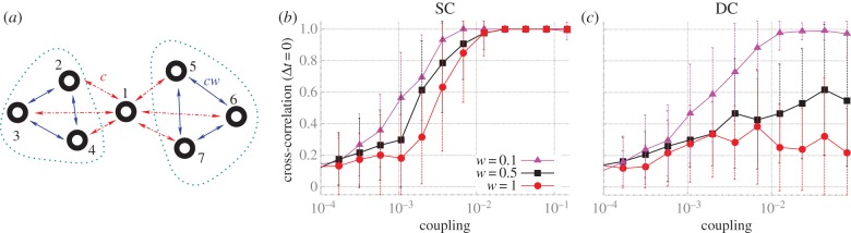
Maximum zero-lag synchronization in larger modular structures. (a) Canonical modular network with one hub (node 1) and two clusters (composed of nodes: 2, 3 and 4; 5, 6 and 7). The connections between hub-cluster nodes (red dotted lines) have strength c, and cluster–cluster connections (blue lines) have strength cw. (b) Maximum zero-lag synchronization between nodes from the SC. (c) Maximum zero-lag synchronization between nodes located at DCs. (Online version in colour.)