Figure 2.

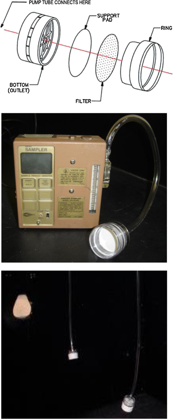
Diagram of the bioaerosol sampling cassette assembly (top), photograph of a cassette attached to a sampling pump (centre) and photograph of the cassettes in operation in the cough chamber (bottom).

Diagram of the bioaerosol sampling cassette assembly (top), photograph of a cassette attached to a sampling pump (centre) and photograph of the cassettes in operation in the cough chamber (bottom).