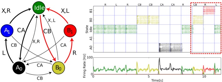
Figure 4.

Soft State Machine implemented in neuromorphic hardware. (Left): State machine description of a cognitive task (Neftci et al., 2013). Each state is represented by a circle and each arrow is a possible transition given the annotated symbol. The symbol × reflects an “invalid” cue and resets the state to “Idle.” The spiking neural network architecture underlying the SSM is composed of three sWTA circuits: a state sWTA that maintains the state in persistent activity (32 neurons per state), a transition sWTA that mediates the transitions between states given the input symbols (16 neurons per symbol). The colored arrows in the state diagram indicate the path followed when the sequence CB, R, L is presented. (Right): State population activities recorded from a multi-chip neuromorphic setup. From top to bottom, raster and population firing rates of the state populations, raster and populations firing rates of the output populations. The labels situated above the top raster plot indicate the presented symbols. One valid sequence (CB followed by R,L) is detected at t = 12 s, as highlighted by the red box.
