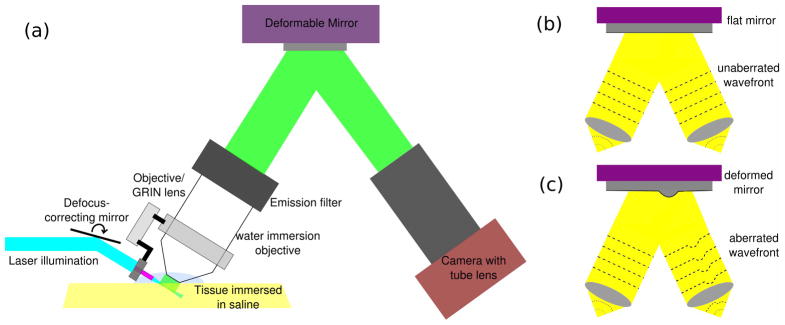
Fig. 1.

AO-OCPI schematic: (a) The experimental setup for AO-OCPI microscope. A DM is placed behind the back aperture of the objective. The light reflected off the DM is imaged onto a camera. (b,c) Schematic of wavefront aberration when the DM is “flat” and when one actuator on the DM is moved.
