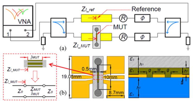
Fig. 1.

(a) A schematic of the RF sensor under test. (b) The top and cross section views of the sensing zone, where w = 6 μm, g = 7.2 μm, t = 0.5 μm (gold), h1 = 50 μm (channel), h2 = 1 mm, h3 = 2 mm (PDMS), ε1: MUT permittivity, ε2: 3.75, ε3: 2.3.

(a) A schematic of the RF sensor under test. (b) The top and cross section views of the sensing zone, where w = 6 μm, g = 7.2 μm, t = 0.5 μm (gold), h1 = 50 μm (channel), h2 = 1 mm, h3 = 2 mm (PDMS), ε1: MUT permittivity, ε2: 3.75, ε3: 2.3.