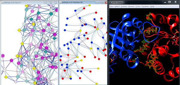
Figure 7.

Visualization of the dimer interface with focus on the mutated residues. The combined visualization of the conservation-colored RIN of chain A of scTIM (left), the residue nodes in the interface between chain A (red) and chain B (blue) of scTIM (middle), and the ribbon representation of scTIM are in the same colors as provided by UCSF Chimera (right). Mutations located in the dimer interface (V86, T45, S71, S16, Q82, N78, L13, H103, F108) are highlighted by yellow colored nodes in the network views and by green boundaries and ball-and-stick representations in the structure view. Nodes that correspond to mutated residues are depicted as diamonds.
