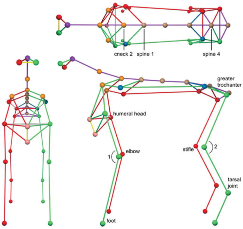
Fig 3.

3-D reconstruction showing “ball and stick figures”. Top—Truncal sway was calculated utilizing 2 vectors. Vector v1 from cneck2 to spine1, Vector v2 from cneck2 to spine4. The maximum and minimal angles were the angles made between these two vectors in the y-plane. Bottom—Elbow flexion and extension was defined by the minimum and maximum angle created by the markers located at the level of the humeral head, elbow, and front foot (angle 1). Stifle flexion was determined based on the minimum and maximum angle created by the markers located at the greater trochanter, stifle joint, and tarsal joint (angle 2).
