
Figure 1.
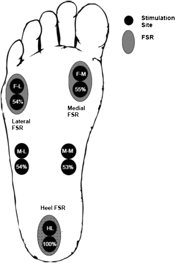
Cartoon schematic illustrating the positions of the paired stimulation electrodes (solid circles) for the 5 sites: HL (S1), M-M (S2), M-L (S3), F-M (S4), and F-L (S5). The position of the force-sensing resistors (FSRs) are shown as the hatched ovals at heel (F1), medial (F2), and lateral (F3) regions. Abbreviations: M-M = mid-foot medial, M-L = mid-foot lateral, F-M = forefoot medial, F-L = forefoot lateral.