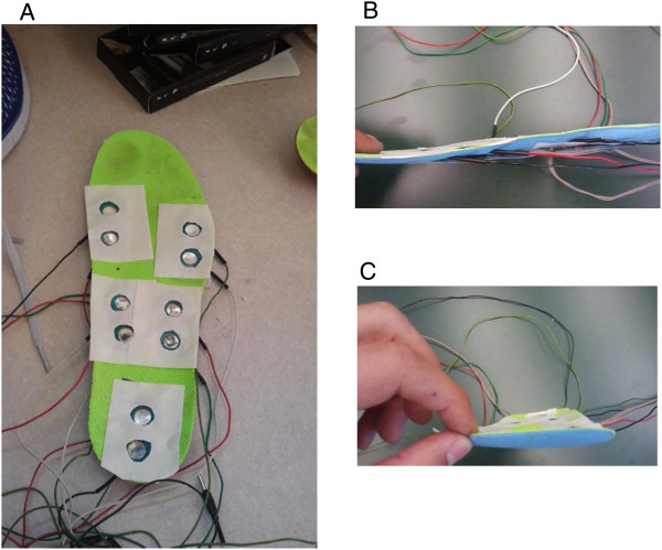
Figure 2.

Photographs showing the configuration of the stimulating electrode array in the sock liner. A. the electrode pairs cut-out from the sock liner and overlaid with 2 sided tape; and profile of the integrated sock liner with electrode pairs and FSRs shown from the medial side (B) and from the front (C).
