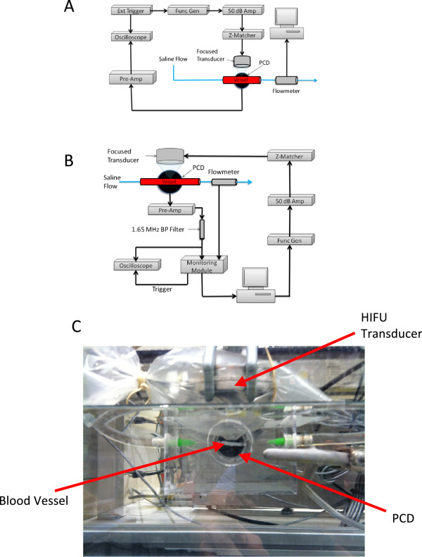
Figure 1.

Schematic showing experiment layout, experimental setup for rupture suppression, and Intra-procedural photograph showing positions of HIFU transducer. (A) Schematic showing the experiment layout for rupture prediction trials. (B) Experimental setup for rupture suppression trials utilizing active feedback using a custom control module. (C) Intra-procedural photograph showing positions of the HIFU transducer, PCD, and ex vivo vessel.
