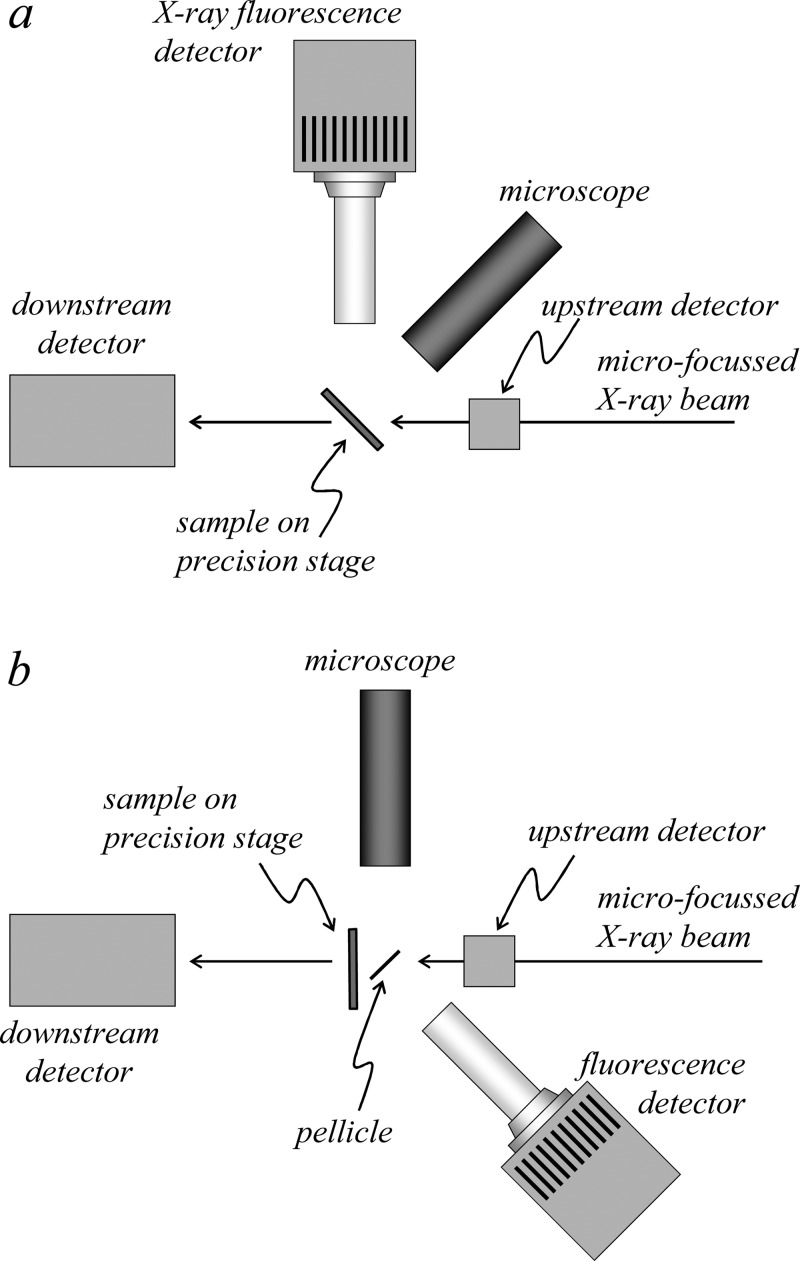
Figure 17.
Plan view schematic diagrams of different sample geometries for X-ray fluorescence imaging. The geometry shown in (a) has the plane of the sample oriented at 45° to the incident beam, while that shown in (b) has the sample plane oriented at normal incidence to the illuminating X-ray beam.

