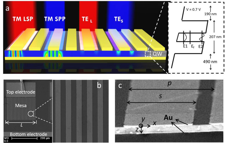
Figure 1. Schematic diagraph of the PCQWID.
(a) The incident TM and TE polarized lights have different coupling behaviors to form different cavity modes. The figure shows the electric field distributions of TM LSP (Localized Surface Plasmon) mode at its calculated resonant wavelength of 14.9 μm, TM SPP (Surface Plasmon Polariton) mode at its calculated resonant wavelength of 12.4 μm, and TE modes at the same wavelength of 14.9 and 12.4 μm, respectively. The right panel is the schematics of the active layer. The first two energy levels of the single QW are separated of 97 meV, corresponding to a wavelength of 12.7 μm. (b) SEM image of the cleaved facet of the cavity structure. Geometrical parameters are designed as p = 9.2~10.6 μm, s = 4.9~5.9 μm. Both the top and bottom Au layers are 100 nm thick. (c) SEM image of a fabricated PCQWID, the grating covering area is 230 × 200 μm2.

