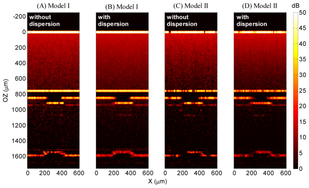
Fig. 12.

Comparison of the simulated OCT images of alumina obtained by both model I and II for λ = 4 µm, with and without account of dispersion. The vertical axis represents the optical distance as shown to the far left and the color-coded calculated intensity is given to the far right.
