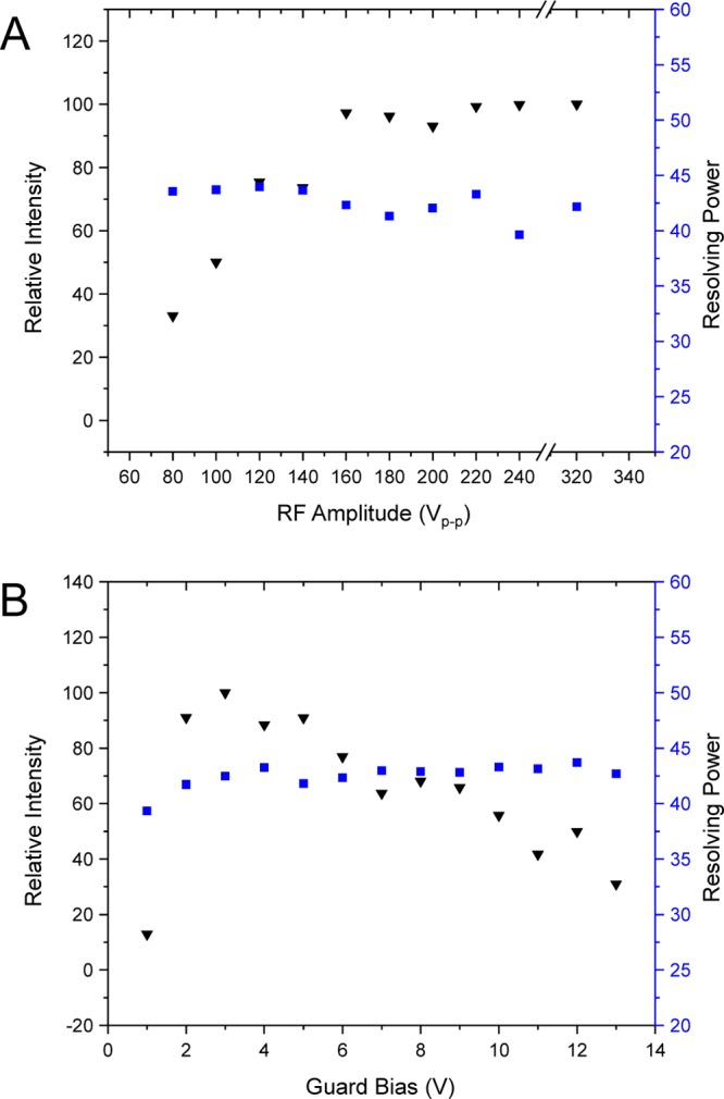
Figure 4.

(A) Effects of RF amplitude on relative intensity (inverted black triangles) and resolving power (blue squares) for m/z 922 in the linear arrangement. The guard bias was set to 5 V above the first and last RF electrode. The RF frequency was 750 kHZ. (B) Effects of guard bias voltage on relative intensity (black inverted triangles) and IMS resolving power (blue squares). The guard bias was set to the desired voltage the same magnitude above the first and the last RF trace. RF was 750 kHz, 220 Vp-p.
