
Figure 1.
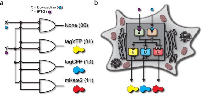
(a) Boolean logic illustration of a biological decoder with chemical inputs and fluorescence proteins as the outputs of the genetic circuit. (b) Node and edge schematic of the decoder circuit within a cell. The system consists of five distinct nodes combined into two distinct layers which interact through activation and inhibition edges. Nodes A and B comprise the “regulating” nodes, while nodes C, D, and E comprise the “regulated” nodes.