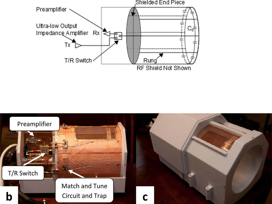
Figure 2.
(a) Diagram of the array coil setup showing the rung elements with the decoupling capacitor at the end opposite the coil feed. The preamplifiers and t/r switches are mounted on the coil as indicated and shown in b. The elements are shielded and a shielded end piece (labeled and shaded) prevents stray RF from interacting with the hardware behind. (b) Outside view of the array coil showing the array hardware. (c) Fully assembled array coil shown in its completed housing.

