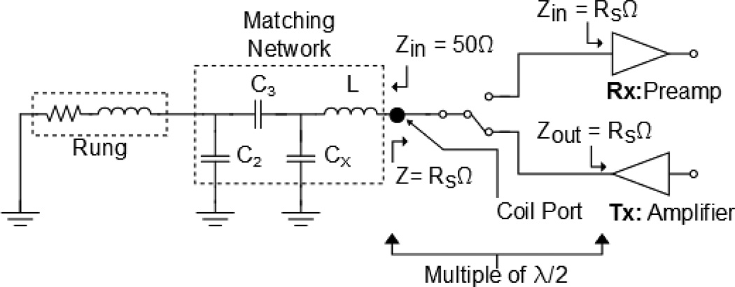
Figure 3.
Block diagram of the transmit/receive configuration of the array and matching network. During transmit and receive, the coil is presented with a low input impedance that places the inductor L in parallel with the equivalent capacitance of the matching network, creating a trap and suppressing induced currents. The electrical lengths between the coil port and the amplifier/preamplifier are a multiple of a half-wavelength to prevent an impedance transformation. The matching network used was presented in [1].

