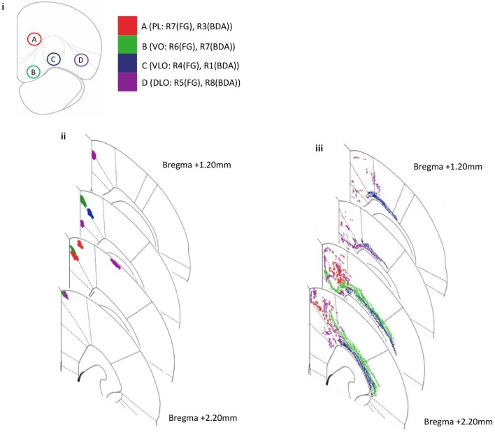
Figure 3.
Diagram representing amalgamated injection sites within PFC and subsequent projection sites to sensory-motor cortex for both anterograde (BDA) and retrograde (FG) tracer injections in several rats. Coronal sections depict the injection site and projecting site. (i) The positions of four injection sites within PFC; PL (injection A: R7(FG), R3(BDA)), VO (injection B: R6(FG), R7(BDA)), VLO (injection C: R4(FG), R1(BDA)) and DLO (injection D: R5(FG), R8(BDA)). (ii) Anterograde labeling of axon terminals (PFC output connections) following injections into four PFC sites (A–D BDA: R1, R3, R7, R8). (iii) Retrograde labeling (PFC input connections) following injections into three PFC sites (A–D, FG: R4, R5, R6, R7). Note the ordered location of labeled areas/neurons within the dorsal-ventral and medial-lateral axes.

