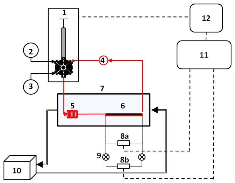
Figure 1.

Schematic view of the viscometry system. (1) Programmable single-syringe pump connected to a 6-way distribution valve, (2) solvent reservoir, (3) waste container, (4) solution vial and top head stirrer, (5) stainless steel loop for temperature equilibration, (6) pressure tubing, (7) water bath, (8 a,b) differential pressure sensors, (9) low range pressure sensor protection valves, (10) Water pump, (11) Data acquisition Module, (12) personal computer.
