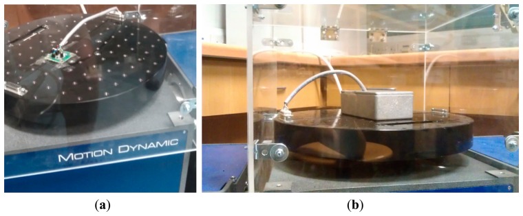
Figure 8.

Test setup for characterization of the proposed angular rate sensor. (a) the PCB with the sensor is mounted on top of the rate-table; (b) the PCB with the sensor is placed in an aluminum box and mounted on top of the rate-table. The aluminum box ensures electromagnetic shielding of the device under test so as to avoid picking up electrical noise emitted from the rate-table motor.
