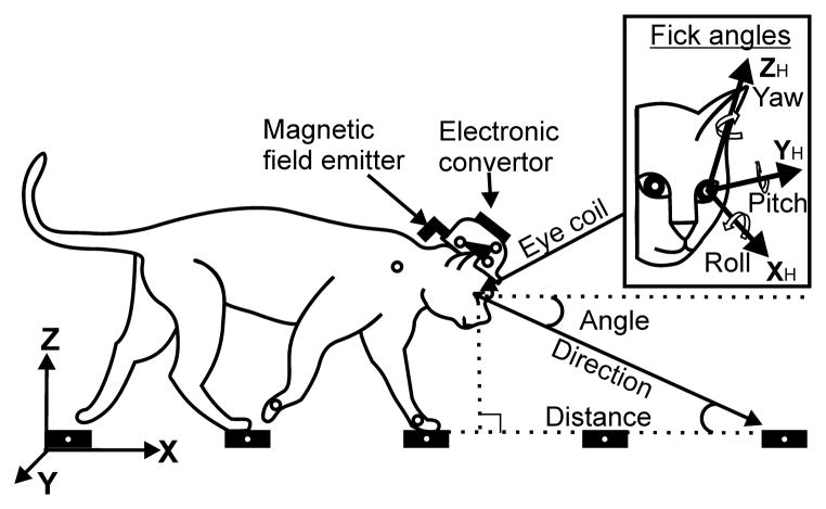
Figure 2.
Coordinate frames. The chamber-related global (X, Y, Z; “head-in-space”) coordinate system is shown in the left bottom corner, and the head-related “Fick” coordinate system (“eye-in-head”; XH, YH, ZH; Fick, 1954) is shown in the insert. Positions of the magnetic field emitter and electronic converter on the cat’s head are indicated. The emitter antenna is placed behind the head and oriented orthogonally to the plane of the eye search coil. Approximate positions of LEDs on the head, forelimb right shoulder, right and left wrists, and cross-pieces of the ladder are shown by small circles. Gaze angle, direction, and distance to intersect with the walking surface are schematically shown for the XZ plane.

