Figure 1.

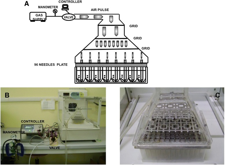
Air-Well minifermenter scheme/layout. A) schematic representation of the Air-Well minifermenter. B) the Air-Well minifermenter. C) Magnification of the Plexiglas bell with the grid used to equally split the air flux.

Air-Well minifermenter scheme/layout. A) schematic representation of the Air-Well minifermenter. B) the Air-Well minifermenter. C) Magnification of the Plexiglas bell with the grid used to equally split the air flux.