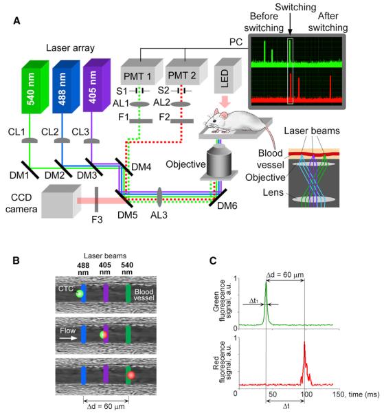
Figure 1. Principles of Multicolor PFC.
(A) Schematic of the setup, together with signal traces in the green and red channels before, during, and after photoswitching (upper right inset) and a diagram of the alignment of the laser beams on the sample (lower right inset). CL, cylindrical lens; DM, dichroic mirror; F, bandpass filter; AL, achromatic lens; S, mechanical slit; PMT, photo-multiplier tube, and PC, a computer.
(B and C) The underlying principle (B) and PFC traces (C) of photoswitching and detection are depicted.

