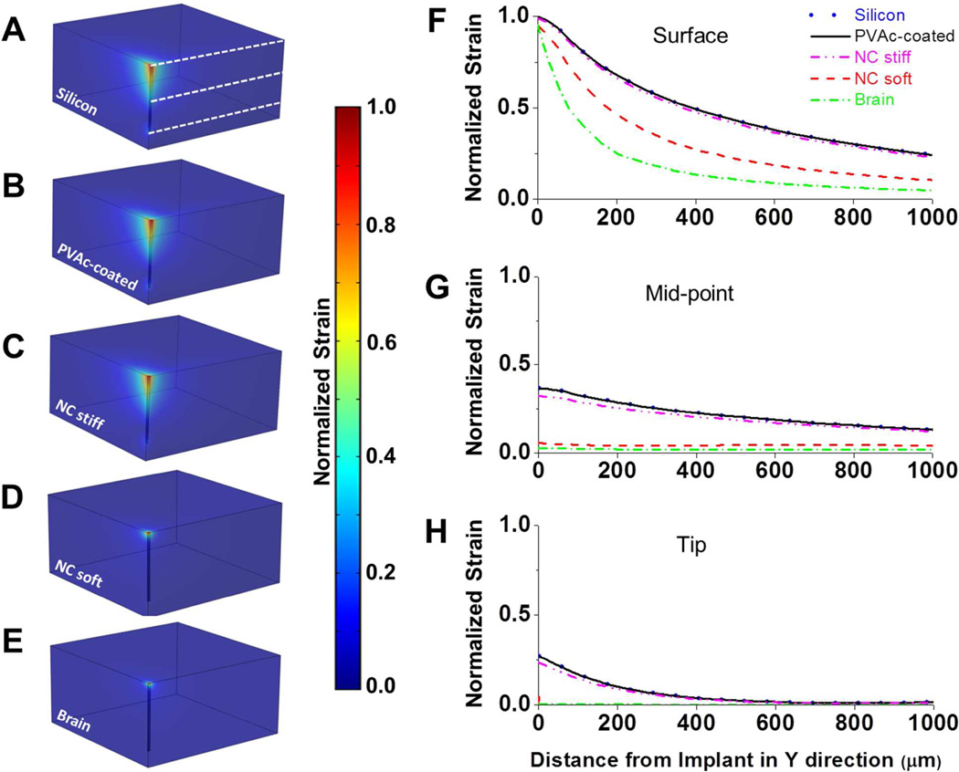
Figure 2.
(A–E) Predicted strain profiles induced by a tangential tethering force on (A) a bare silicon implant (E’ = 200 GPa), (B) a silicon implant with a 15.5µm PVAc coating (E’ = 78 GPa), (C) an implant created entirely of the PVAc nanocomposite material (63µm × 130µm) in the stiff state (E’ = 5 GPa), (D) an implant created entirely of the PVAc nanocomposite material (63µm × 130µm) in the compliant soft state (E’ = 12 MPa), and (E) a hypothetical implant that matches brain modulus (E’ = 6 kPa). Strain profiles are normalized to the maximum induced strain surrounding the uncoated silicon probe. (F–H) Normalized strain profiles extending in the positive y-direction are taken from the brain surface, the implant’s midpoint and implant’s tip (levels are shown as white dashed lines in (A)). No significant differences were seen between the bare and coated silicon implants and stiff NC. Despite the nanocomposite implant having larger dimensions, the model demonstrated that the compliant nanocomposite implant would induce less strain on the surrounding tissue than both the uncoated and coated Si implants along their entire length. Additionally, no significant differences were seen between the compliant nanocomposite and a (hypothetical) implant with a modulus that matches the one of the cortical tissue at the midpoint and tip levels.

