Figure 1.

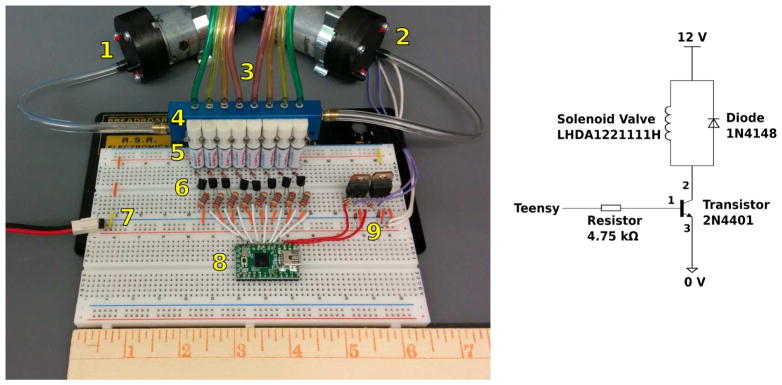
Figure 1A: Picture of the arrangement showing the pneumatic circuit (1–2: pneumatic pumps, 3 pneumatic connections to the device, 4: manifold, and 5 solenoids), and the electronic circuit (7: power, 8: Teensy, and 9 transistors to control the pneumatic pumps).
Figure 1B: Electric circuit designed to control the solenoid valves.
