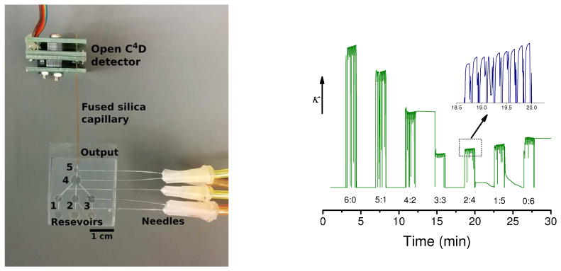
Figure 4.

Figure 4A: Picture of the device fabricated in PDMS/glass and interfaced with a conductivity detector. The device consists of 3 sample inlets, five microvalves, and one sample outlet.
Figure 4B: Relative conductivity values of the solution resulting from mixing different ratios of NaOH and HCl, each at a concentration of 10−3 M.
