
Fig. 1.
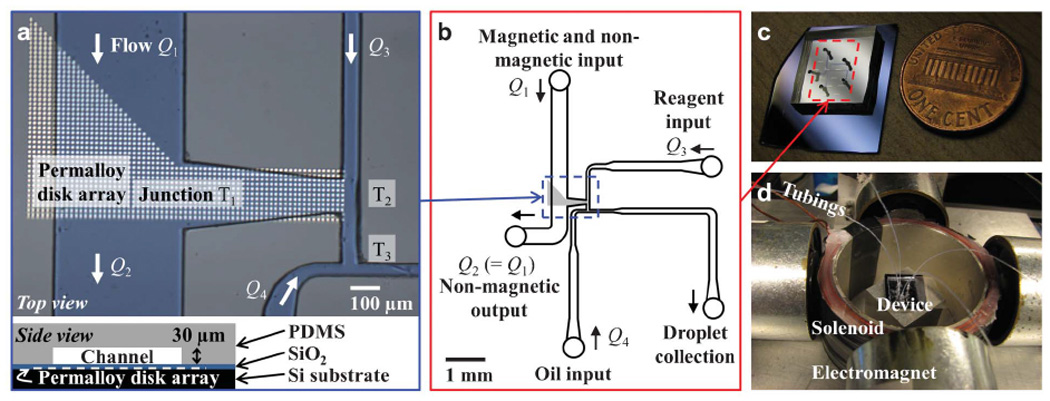
Device layout and system setup. (a) Microscope image (top) showing the channel layout on an array of permalloy (Ni0.8Fe0.2) disks and a schematic side view of the device (bottom). Fluid flow rates Q1, Q2, Q3 and Q4 are indicated at corresponding channels while the three T-junctions are labeled with T1, T2 and T3. (b) Schematic of full layout of the microfluidic channel. (c) Photograph of the device. (d) Photograph of the system consisting of four electromagnets and a solenoid that apply external magnetic field on the device. Tubings connected to computer-controlled syringes transfer fluid to or from the microfluidic channels of the device situated within the setup.