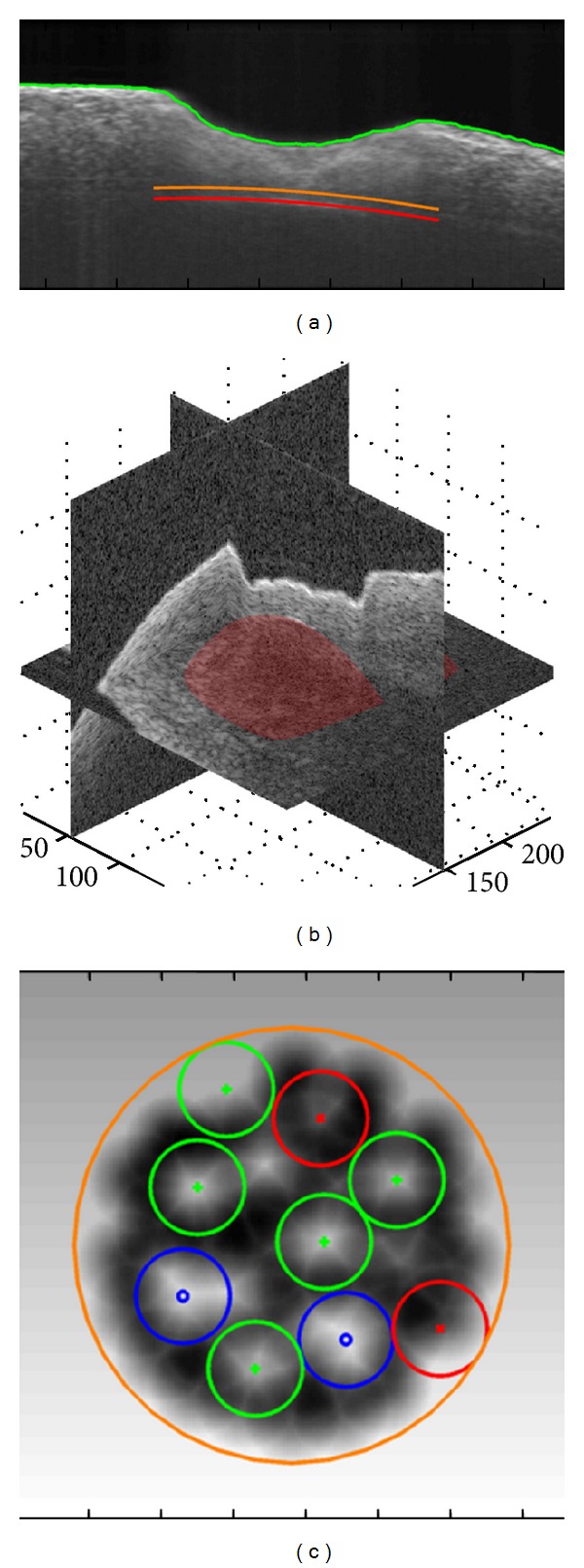
Figure 6.

(a) The position of the bone surface (green), segmented bone-endosteum-perilymph boundary (red), and the user defined “stop surface” of the laser ablation (orange); (b) reconstructed 3D model of the critical structure; (c) ablation pattern planned according to the residual bone thickness map, where the blue, green, and red pulses are corresponding to long, middle, and short pulses; the gray scale in the background denotes the local residual bone thickness (lighter color for larger thickness).
