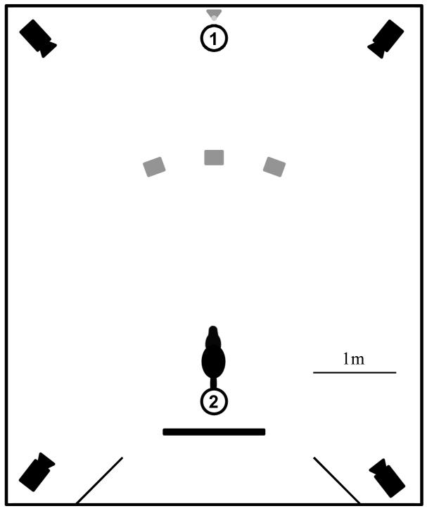
Figure 1. Experimental setup.
The circles represent start positions for experimenters 1 and 2, the grey squares mark locations of the three target boxes, and the grey triangle marks the start and end location of the displacement device. The partition behind experimenter 2 is used during control trials (cf. Procedure section of Methods). The setup (with the exception of the cameras) is drawn to scale.

