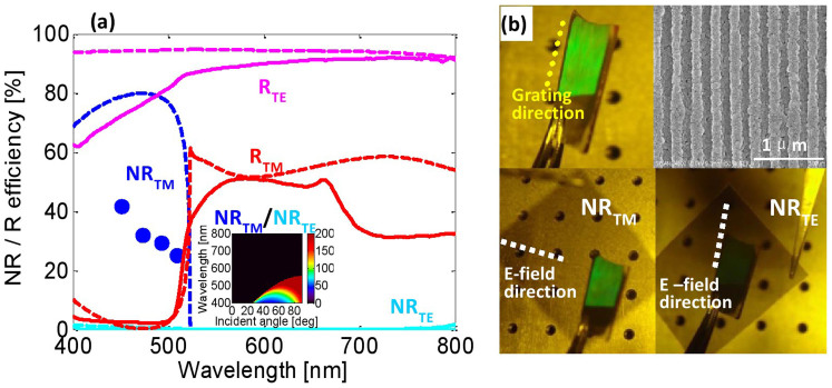
Figure 5. Spectra and photos of a 280-nm-pitch grating.
(a) Measured (solid lines) and simulated (dashed lines) NR (blue and cyan lines) and reflection (red and magenta lines) spectra for TM (blue and red lines) and TE (cyan and magenta lines) light with an incident angle of 60°. The inset is the simulated extinction ratio of NRTM/NRTE. (b) Photos of the device irradiated by un-polarized white light with an incident angle of approximately 60° and filtered by a polyvinyl alcohol (PVA) plastic polarizer (extinction ratio of 300). The yellow dotted line indicates the direction of the grating lines. The white dashed lines illustrate the electric field direction of the light passing through the polarizer. An SEM image of the device is also presented. The dielectric grating in the device was fabricated by laser interference, with an Al thickness of 50 nm.

