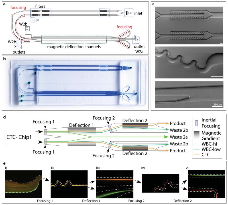
Figure 4.
Structure of CTC-iChip2. (a–c) CAD drawing (a), high-resolution photograph (b) and electron micrographs (c) of CTC-iChip2. Highlighted are inlet and outlets, filters, focusing regions and magnetic deflection channels (width • length of magnetic deflection stage 1 = 1 mm • 37 mm; width • length of stage 2 = 0.5 mm • 37 mm). Scale bars, 250 μm. W2, waste 2a; W2b, waste 2b; P, product. (d) Schematic of CTC-iChip2. Note that, for simplification, the schematic was linearized; in the actual device, before entering the second stage, fluid flow turns around 180° and thus moves in the opposite direction of the first stage. (e) Fluorescence images of cell streaks formed during CTC-iChip2 operation showing both stages of inertial focusing and magnetophoresis of WBCs with (green) or without (orange) magnetic load. CTC-iChip2 initially separates the flow equally into two parallel and equivalent channels for higher throughput. Cells get tightly focused in the inertial focusing region, and subsequently separated in the magnetophoresis region (dashed lines symbolize channel wall). In the first separation stage, the magnetic force is directed toward the middle of the channel, and thus labeled cells deflect toward the middle and exit through waste 2a (d, Fig. 5). The first magnetophoresis stage is designed to have a relatively lower magnetic gradient, as a result only the portion of the WBC population with more than seven beads is successfully deflected. Channels on each side of waste 2a lead to the second stage, where cells are refocused and deflected with higher sensitivity (cells with more than two beads are deflected). Separated populations exit through their respective outlets (WBC → waste 2b, CTC → product).

