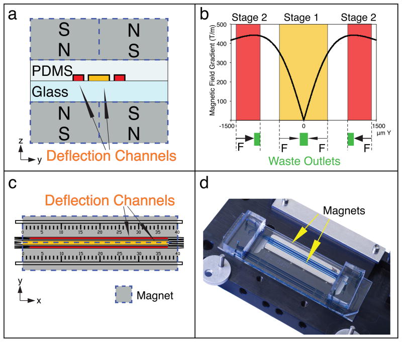
Figure 5.
Magnetophoresis setup. Deflection channel positioning in the CTC-iChip2 magnetic manifold is crucial in the success of the protocol. (a) zy plane schematic of the magnetophoretic setup for both stage 1 (yellow) and stage 2 (red). (b) The plot on top shows the calculated magnetic field gradient on points across the y axis, where the indicated stages of the deflection channels are. Stage 2 positioning is designed to enable the highest sensitivity separation possible, whereas stage 1 positioning is designed to push the cells toward the middle with a softer magnetic field gradient. (c) CTC-iChip2 design includes a ruler to help align CTC-iChip2 with its magnetic manifold. (d) When aligned, the stage 1 deflection channel is positioned in the middle of two magnets.

