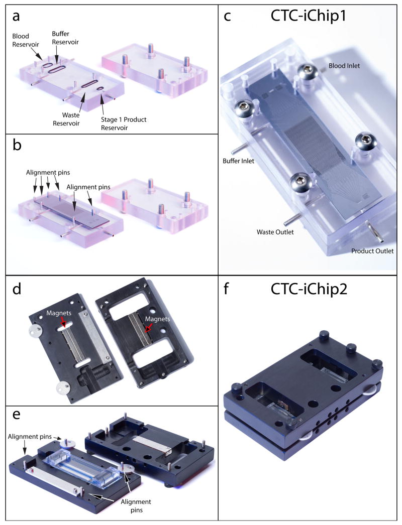
Figure 7.
CTC-iChip assembly. (a) CTC-iChip1 manifold bottom piece with inlet and outlet O-rings attached (left) and top piece with screws in place (right). (b) CTC-iChip1 is placed on top of O-rings and fits between the metal guide posts. Fluid reservoirs, O-rings and CTC-iChip1 inlets are automatically aligned in this step. (c) The top piece is screwed into the bottom piece with the chip. (d) CTC-iChip2 manifold bottom piece (left) and top piece (right). CTC-iChip2 manifold houses the permanent magnets oriented to form a quadrupole (Fig. 5). (e,f) CTC-iChip2 is placed on the manifold bottom piece (e), is aligned (as detailed in Fig. 5 and Supplementary Video 2) and the top piece is pushed and screwed in f. When connected with tubing, these assembled devices form the CTC-iChip (Fig. 8).

