
Figure 16.
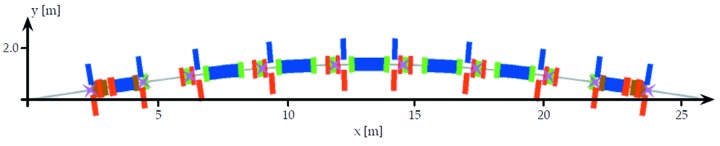
Achromat schematic with placement of beam position monitors indicated as magenta crosses, and horizontal/vertical correctors indicated by blue and red strips. Note that this schematic has two vertical correctors in matching cell 1, but one of these (between OYY and SDend) was removed in order to allow passage of the photon beam pipe.