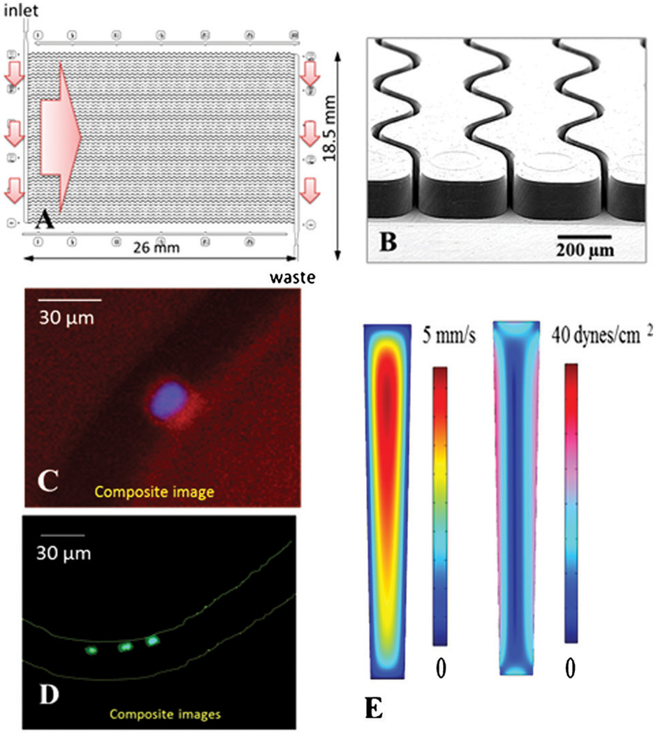
Fig. 5.
(A) Schematic operation of the CTC selection module with 50 parallel, sinusoidal microchannels and inlet/outlet channels arranged in the z-configuration. The large arrow indicates sample flow direction through the selection channels. (B) SEM of the selection bed showing high-aspect ratio (30 × 150 µm, w × d) sinusoidal microchannels and the output channel. (C) Composite fluorescence images of a CTC stained with DAPI(+), CK8/19(+), and not with CD45(−). (D) Four WBCs staining positively for DAPI(+) and CD45(+) and negatively for CD8/19(−). (E) Fluid dynamics simulation results showing the distribution of flow velocities and shear stress in microfluidic selection channels.

