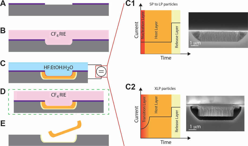
Figure 1. Schematic representation of the MSV fabrication process.
A) Fabrication began with a silicon rich silicon nitride layer. B) Patterning in CF4 yielded an array of 2 µm diameter holes with pitch of 2 µm. C) A reactive ion etch formed pores corresponding to photolithographic holes from the previous step. Graphs on right show the effect of current applied over time for SP to LP (top) and XLP (bottom) with SEM images depicting porosity. D) The optional removal of the nucleation layer was performed in a reactive ion etch with CF4. E) MSV particles were released after etch with CF4.

