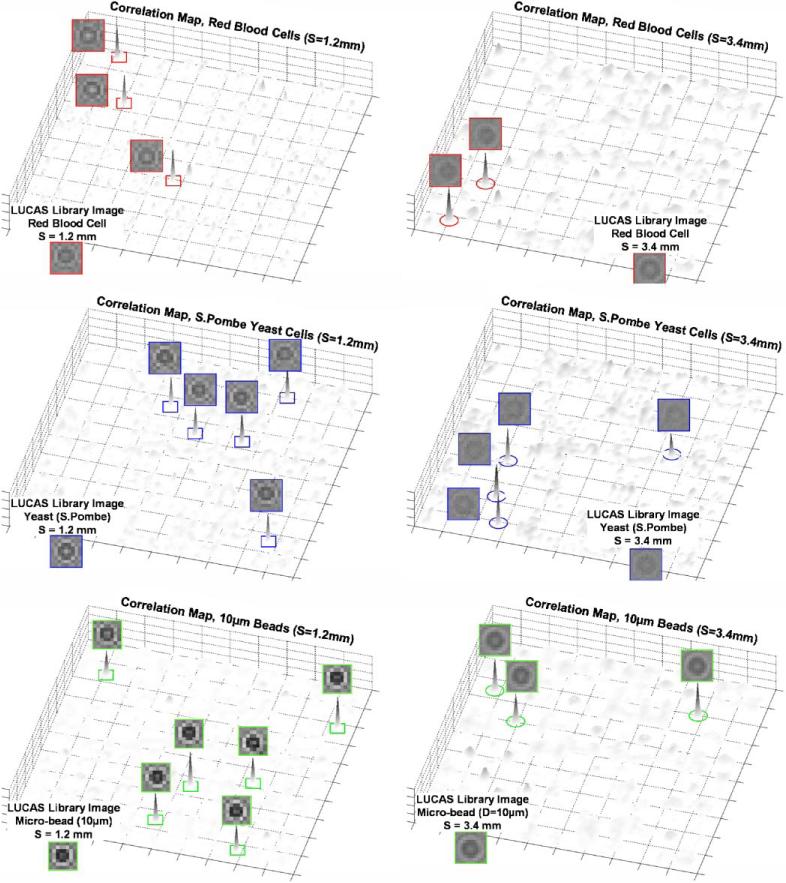
Figure 9.
The 2D correlation maps are illustrated for the LUCAS experiment shown in Figure 8. The left panel shows S = 1.2 mm plane whereas the right plane shows the S = 3.4 mm plane. For each plot, the LUCAS library image of the target micro-object is also shown at the bottom. Notice that the noise floor for the longer DOF (S = 3.4 μm) is higher for all the micro-objects; however, the correlation peaks of the target objects with the LUCAS library image is quite strong, yielding to the correct decision=regardless of the increased noise floor. [Color figure can be seen in the online version of this article, available at www.interscience.wiley.com.]

