Abstract
Organizing a material into well-defined patterns during the dewetting process provides an attractive micro-/nano-fabrication method without using a conventional lithographic process, and hence, offers potential applications in organic electronics, optics systems, and memory devices. We report here how the mechanical modification of polymer surface by an Atomic Force Microscope (AFM) can be used to guide thin film dewetting evolution and break the intrinsic spatial correlation of spontaneous instability. An AFM is used to implement the mechanical modification of progressively narrow grids to investigate the influence of pattern size on the modulation of ultrathin polystyrene films dewetting evolution. For films with different initial thicknesses, when grid size is close to or below the characteristic wavelength of instability, the spinodal dewetting is suppressed, and film rupture is restricted to the cutting trench. We will show in this paper it is possible to generate only one droplet per gridded area on a thin film subsequent to nucleation dominated dewetting on a non-patterned substrate. Furthermore, when the grid periodicity exceeds the spinodal length, the number of droplets in predefined areas gradually approaches that associated with unconfined dewetting.
Organizing a material into well-defined patterns during the dewetting process provides an attractive way of fabricating micro- or nano-structures without using a conventional lithography process1,2. This phenomenon has been observed widely in a variety of materials1, e.g., polymers3, organic semiconductors4 and metals5,6. The characteristic length scales of the structures generated could be controlled by adjusting the initial film thickness1,7 or the surrounding mediums, e.g., air8, solvent vapor, solvent9 or water-organic solutions7, to influence the intermolecular forces or alter the surface tension. Hence, understanding and controlling the dewetting process in the micro and nano scales offers potential applications in organic electronics4,10,11, optics systems5, and memory devices12.
Theoretical explanations and experiments associated with structured patterning by dewetting have been previously investigated9,13,14,15,16,17,18,19,20. When the spinodal parameter is negative, i.e., ∂2Φ(h)/∂h2 < 0, where Φ(h) is the effective excess free energy of per unit area and h is the film thickness, spontaneous instability is triggered on a uniform ultrathin film. This results in film rupture, formation of holes and coalescence into droplets. However, the dewetted structures are distributed randomly with the spatial correlation and the wavelength of long-wave instability being given by16
 |
where γ is the interfacial tension. Several strategies have been proposed to realize a long-range order in dewetted structures via physical, chemical or physicochemical methods. A physical constraint can be introduced from the upper or lower surface of the film by a topographically patterned substrate7,21,22. Directly spinning a film on the topographically patterned substrate induces a slight variation in thickness23 and, therefore, the spinodally stable film turns unstable whenever the local thickness satisfies the condition of ∂2Φ(h)/∂h2 < 02. A chemically patterned substrate3,4,24 or a locally modified polymer property by an electron beam (e-beam)8,25 can also be used to guide the dewetting process by the spatial gradient of wettability2,26 or viscosity difference25. Despite the impressive results obtained through these control mechanisms, the majority still rely on photolithography or e-beam lithography to fabricate molds or masks. Material directly patterned by electron or ion beam lithography suffers from local property variation25, proximity effect, and radiation-induced crystal damage27 which should be avoided in optics and electronic nanostructure fabrication. The material selectivity of e-beam lithography restricts this universal dewetting phenomenon to narrow practical applications. Studies have also shown that the lateral confinement of substrate pattern by these approaches is rather mild for a spin coated film22 and influenced by the width of heterogeneous structures or chemically modified areas and the match between substrate periodicity and spinodal length scale of dewetting2,26,28.
Mechanical modification of a sample by means of cutting or plastic deformation using an atomic force microscope (AFM) has received increasing interest in nanostructure fabrication. This method is low cost, highly precise, and demonstrated good environmental and material compatibility. By employing such a tip-based nanofabrication approach, sub-50 nm structures have been fabricated on various samples (e.g. polymer, semiconductor and metal)29.
We first report here how the mechanical modification of polymer surface by AFM can be used to guide thin film dewetting evolution in acetone and break the intrinsic spatial correlation of spontaneous instability. The positions of dewetted droplets can be confined in specific predefined locations under the influence of the AFM cutting trace. This controllability is enhanced as set-point force or trench depth increase. We studied the influence of mechanical modification on the evolution of dewetting patterns by modulating PS film with different thicknesses and cutting grid designs from 0.5 μm × 0.5 μm to 16 μm × 16 μm. Micro and nano-scale droplet arrays were realized by adjusting properly the periodicity of the cutting grid. An annealing treatment was applied to modify droplet morphology, thus leading to a spherical profile and offering a method for the fabrication of micro- and nano- lens arrays.
Experimental
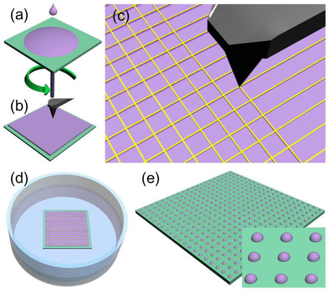
Figure 1 provides a schematic of the AFM mechanical modulation controlled dewetting process. First, polystyrene (PS, Mw = 123 kg/mol, Mw/Mn = 1.08, from Alfa Aesar) was dissolved in toluene, filtered by 0.2 μm PTFE filters and spin-coated onto a cleaned glass substrate; the resulting thin film thickness was ~12 ± 0.2 nm or ~26 ± 0.2 nm, and the surface roughness of the film was ~0.2 nm (measured by AFM) [Figure 1(a)]. After drying in air for 2 hours, the spin-coated film was annealed on a hotplate at 75°C for 8 hours to minimize residual stresses developed during spin coating, which could induce undesirable rupture even for an energetically stable film30. Mechanical modification was conducted by Veeco Dimension 3100 AFM in the closed loop contact mode [Figures 1(b) and (c)] with velocity equaling 120 μm/s. A commercially available tapping mode cantilever with a doped diamond coated tip, whose radius of curvature of 35 nm was used. The spring constant and the resonant frequency of the cantilever were 42 N/m and 320 kHz, respectively. We captured images of fabricated features using another cantilever without coating, which had its properties similar to the coated one but had a radius of curvature of 8 nm in the tapping mode. After mechanical modification, the thin film with predefined patterns was immersed in acetone [Figure 1(d)] for 15 s; the film thickness was ~12 nm and ~26 nm when the immersion time was changed to for 30 s. This difference in dewetting times was chosen in view of the quick evolution of the thinner film9. After drying in air, a stable array of PS dots was obtained [Figure 1(e)]. Liquid acetone was used here in view of the observation that a reduction in the stabilizing interfacial tension of PS and van der Waals interaction under liquid acetone9 can significantly reduce the length scale of instability according to Eq. (1). This helped the progress of dewetting despite severe confinement25.
Figure 1. Experimental process used in AFM-based mechanically controlled dewetting.
(a) PS film was spin coated onto a glass substrate. (b) and (c) Patterned PS trenches predefined by AFM mechanical modulation. (d) Mechanically modulated PS film dewetted in acetone. (e) Dewetted droplet array on glass substrate.
Results and Discussion
Unmodulated PS film dewetted in acetone
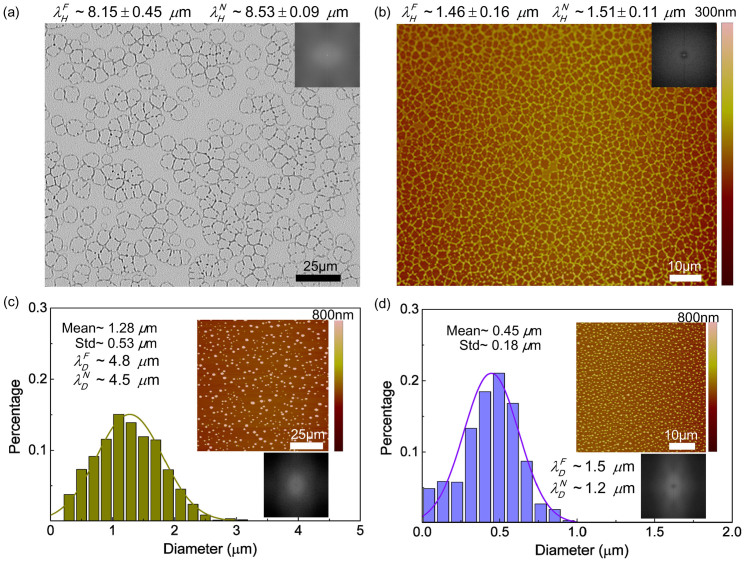
On a flat homogeneous substrate, dewetting of an unmodified ultrathin polymer film is engendered by the destabilizing intermolecular forces16. Time evolution of unconfined PS film dewetted in liquid acetone at room temperature has been studied before. It has been found that the long-range van der Waals force plays a stabilizing role whereas the polar interaction induces surface instability in the film when the film thickness is below a threshold value2,9,26. Owing to poor penetration in polymer of the solvent (acetone) molecules, the glass transition temperature of PS is reduced, thus allowing reorganization induced by dewetting at the room temperature9. As shown in Figures 2(c) and (d), upon film rupture dominated by spontaneous instability [Figures 2(a) and (b)], the dewetted droplets get distributed on the substrate in a pattern representing a compromise between complete disorder and perfect order20. Note that, for the initial film thickness (h0) of ~26 nm, the mean diameter is 1.28 μm and the standard deviation (Std) is large (0.53 μm, i.e., 41% of the mean value). The mean diameter of the dewetted droplets in Figure 2 (d) is 0.45 μm with a Std of 0.18 μm (40% of the mean value) when h0 decreases to ~12 nm. Fast Fourier Transform (FFT) and the relationship between wavelength λN and the number density of droplets/holes (N), λN = N−1/2, were used to estimate the length scale of the spinodal instability [ and
and  in Figures 2(a) and (b)] and the characteristic wavelength of fully dewetted structures [
 and
and  in Figures 2(c) and (d)].
Figure 2.
(a) and (b) Optical microscope and AFM images of PS films with initial thickness of ~26 nm and ~12 nm dewetted in liquid acetone for ~1 s. The inset images are FFT results. The diameter distribution of dewetted droplets from (c) ~26 nm and (d) ~12 nm thick PS film without any mechanical modification. Insets (upper) in (c) and (d) are AFM images. Insets (lower) are FFT results obtained using ImageJ.  and
and  are the wavelengths or the mean separation between holes or droplets, respectively.
Mechanical modification modulated dewetting
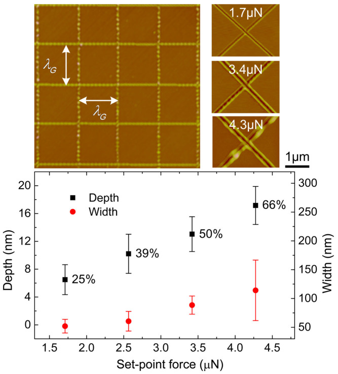
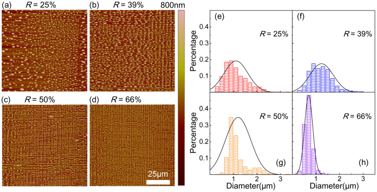
While utilizing the mechanical modification exerted by AFM to modulate dewetting, the first problem that needs to be solved is whether there exists a critical value of cutting force/trench parameter at which the external manifestation of intrinsic instability is effectively modulated. To solve this problem, we studied the ratio (R) of cutting depth to initial film thickness, which can be controlled by adjusting the cutting force applied by AFM (see Figure 3). The parameter R is chosen because the trench parameters (depth, width and curvature of film near trench boundary) could be coupled together by the morphology of the AFM tip, and R can both reflect the influence from the cut trench and initial film thickness. The force influences the controllability of mechanical modification of thin PS film. Figure 4 provides a comparison of dewetted results confined by fixed size (λG = 2 μm) grid patterns with different R (25%, 39%, 50% and 66%). The diameter distributions for each case are shown in Figure 4(e)–(h). The diameters in all histograms were calculated by extracting the perimeter by ImageJ and dividing the result by π. The mean diameters were 1.10 μm, 1.24 μm, 1.20 μm, 0.69 μm, respectively. Several conclusions can be drawn from these results: As R increases, (1) the controllability is enhanced; (2) the consistency of the final structure is improved; (3) orderliness of the dewetted droplets is promoted, i.e., these droplets are confined in the grid position; (4) the mean diameter dramatically decreases when the dewetting process is effectively confined. The small value of mean diameter when R is 25% is due to the appearance of numerous satellite droplets. Adjacent droplets remain connected since the weak controllability or uneven cutting trench prevents complete film rupture at the cutting trench leads to a larger diameter for R = 39%, and 50%.
Figure 3. The relationship between trench parameters (depth, width) and set-point force when h0 is ~26 nm.
25%, 39%, 50% and 66% are the ratios of the trench depth to the initial film thickness.
Figure 4.
(a)–(d) The influence of set-point force or trench depth on the controllability of mechanical modulation in dewetting process. The initial film thickness is ~26 nm. (e)–(h) The distribution of the diameter of dewetted droplets for different set-point forces. (a)–(d) corresponding to (e)–(h), respectively.
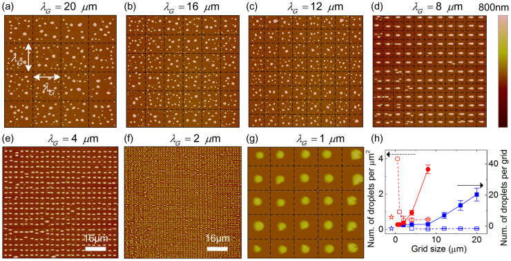
To further study mechanical modulation of the evolution of dewetting, we mechanically modified the PS film by a grid with a different size as shown in Figure 5. When the grid size (λG) changes from 20 μm to 1 μm, the dewetted structures are confined to the predefined site of grid for h0 ~ 26 nm and the number of droplets in each grid reduces until just one is left [Figure 5(h)]. When R = 66%, i.e., mechanical modification by AFM effectively modulates the dewetting evolution, the mean diameter of dewetted droplets increases just as grid size due to mass conversation (Figure 6) when there is only one droplet left in the pre-defined grid area [Figures 5(d)–(f)]. The large standard deviation can be attributed to the appearance of satellite droplets when λG is 8 μm. These satellite droplets may have been derived from the debris induced by mechanical modulation. There is no significant difference in diameter (i.e., 1.10 μm, 1.26 μm, 1.19 μm) for different grid size as R = 25% corresponds to the minimum controllability. The large standard deviation for each grid size following the appearance of satellite droplets recurs with a mechanism different from the case of large set-point force. These diameters are very close to the droplets' in the uncontrolled area [as shown in Figure 1(c)], and the dewetted structures are in a state of transformation from one of intrinsic spatial correlation of spinodal instability to periodicity of mechanical modulation [Figure 4(a)]. Note here that for a ~26 nm film, when λG = 1 μm, it was difficult to obtain long-range ordered droplet arrays due to the accumulation of tip-induced debris for a large R (enhanced controllability). Further, only locally ordered arrays were observed [Figure 5(g)]. Hence the diameter results are not included in Figure 6. At smaller λG values the evolution of dewetting is more sensitive to debris. This points to the need for properly adjusting the relationship between debris and R related to controllability.
Figure 5.
(a)–(g) provide the dewetting results for a film with ~26 nm initial thickness. The size of cutting grid, λG changes from 20 μm to 1 μm. The dashed lines represent mechanically modulated locations, which are not shown in (e) and (f) due to large droplets density. The mean diameters of the dewetted droplets for λG = 20, 16, 12 μm are 1.10, 1.11, 1.09 μm, respectively; the corresponding standard deviation for these mean diameters are 0.64, 0.61, 0.57 μm, respectively. The diameter data for λG = 8, 4, 2 μm corresponds to the case of R = 66% in Figure 6. (h) plots the number of droplets per μm2 (dashed lines) or the number of droplets per grid (solid lines) and grid size for h0 ~ 26 nm (rectangular) and h0 ~ 12 nm (circle). Data marked by open markers correspond to the number of droplets per μm2 for uncontrolled area. The dewetted results for h0 ~ 12 nm are shown in Figure 7.
Figure 6. The relationship between dewetted droplet diameter and initial grid size for different R.
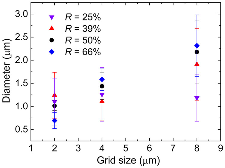
The initial film thickness is ~26 nm.
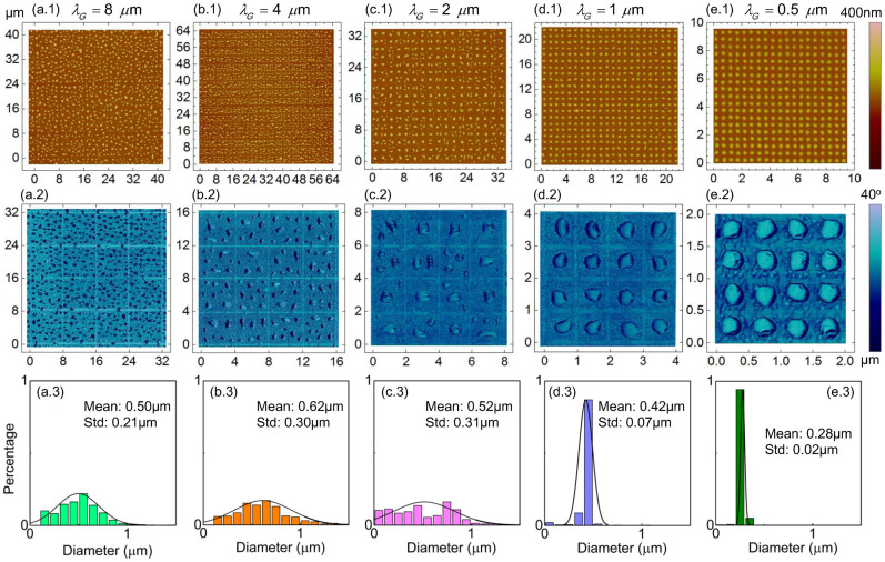
When h0 decreased from ~26 nm (Figure 5) to ~12 nm (Figure 7), similar phenomena appeared during mechanically controlled dewetting, i.e., all films experienced a transition from the longer scale orderliness with local disorder [Figures 5(a)–(c) and Figures 7(a)–(c)] to full orderliness [Figures 5(d)–(g) and Figures 7(d)–(e)]. These phenomena can be explained by a competition between spinodal instability in the film in the cutting grid area and “nucleation” dewetting triggered by mechanical modulation. Such competition between two dewetting mechanisms also appeared in the case of pillar array engendered dewetting2,7. As λG decreased to 8 μm for ~26 nm film and 1 μm for ~12 nm, just about one droplet was left in the cutting grid with a small standard deviation. In such a case, the rupture induced by spinodal instability was suppressed fully. This critical λG corresponding to state transition is denoted as  . As the initial film thickness increases, nucleation induced dewetting occurs first7,16 and, thus, the rupture and dewetting processes initiated by mechanical modification is dominant. Comparing the length scales related to dewetting evolution, which are summarized in Table 1, the critical state transition length
  is close to the length scale of spinodal instability (
 ,
,  , λ) in our study. In other words, when the grid size (λG) is of the same order or smaller than the spinodal length scale of dewetting, the mechanical modulation will dominate and, thereafter, an ordered droplet array appears. The mean diameter and standard deviation of droplets obtained when spinodal and nucleation mechanism coexist as shown in Figures 5(a)–(c) and Figures 7(a.3)–(c.3) are similar to results from unconfined film dewetting which was controlled by spinodal instability [Figures 2(c) and (d)]. As the grid size is increased, the number of droplets per μm2 for mechanically modulated dewetting gradually approaches the number in the uncontrolled area [Figure 5(h)]. All these observations imply that dewetting in the grid areas are gradually dominated by spinodal instability for grid sizes larger than
  .
.
Figure 7. Dewetting results from a ~12 nm thickness film modified by mechanical modulation with different grid sizes (λG = 8 μm, 4 μm, 2 μm, 1 μm and 0.5 μm from left to right).
(a.1)–(e.1) show height images of AFM scanned results. (a.2)–(e.2) are the associated phase diagrams as derived from AFM scanned results. (a.3)–(e.3) are the histograms of diameter for dewetted structures in (a.1)–(e.1). The lateral unit used in (a.1)–(e.1) and (a.2)–(e.2) is micrometer.
Table 1. Comparison between different length scales.
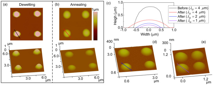
After dewetting the mechanically modulated film in acetone, the droplets generated had large contact angles [Figure 8(c)], which was similar to the results obtained by dewetting a PS film in water-organic solutions7, and had non-ideal spherical contours15. In other words, both in a water-organic solution15 or in acetone as shown in Figure 8(a), there appeared non-ideal spherical contours which were different to the dewetting results of PS by annealing in air or vacuum20 and went against the minimum energy principle. The origin of this non-ideal spherical morphology can be attributed to at least three factors as described below. (1) The surface contamination or physically/chemically heterogeneous surface induced contact angle hysteresis that might disturb the dewetting process by introducing stress at the edges of film rupture area, whose main effect is a distortion of the shape of the dewetted droplets31,32. (2) The disturbance induced structure distortion by liquid flow in solvent (acetone). (3) In addition, the process of extracting the inclined glass substrate from the solvent medium could distort the morphology of the resulting structures. During this process the non-directional flow and uneven volatilization of the solvent will induce the structural variation. The distortion caused by contamination seems to have little influence on our results due to the fact that after annealing at 170°C for 5 h, these dewetted droplets show perfect spherical-like profile as shown in Figures 8(b)–(e). Thus the influence from acetone flow and volatilization are the most likely explanation for the droplet morphology distortion. These ordered micro- or nano- PS droplets array, with perfect spherical-like profile after annealing, holds potential applications in near-field optics to overcome the diffraction limit33, and could also be used as masks to fabricate nanoantenna arrays. The contact angle of dewetted droplets under liquid solvent could also be adjusted by controlling dewetting times13.
Figure 8.
(a) AFM scanned images showing the experimental results following mechanically modulated dewetting in acetone of a ~26 nm PS film. The λG used in this experiment was 4 μm. (b) Annealing result from dewetted droplets shown in (a). (c) AFM scanned profiles corresponding to the cross section in (a), (b), (d) and (e). (d) and (e) Annealing results of dewetted droplets obtained by modulating the PS film with 2 μm × 2 μm and 1 μm × 1 μm grids, respectively. All cases are annealed at 170°C for 5 h.
Conclusions
Our findings have demonstrated that mechanical modulation induced by an AFM tip provides a feasible approach to direct dewetting evolution without destroying or contaminating the substrate from physical, chemical or physicochemical modification. The material compatibility and control flexibility of AFM and dewetting extend the scope of application when these two technologies are combined. The intrinsic spatial correlation of spontaneous instability of dewetting is disturbed when mechanical modification is exerted on the surface of ultrathin PS film. This interference effect is enhanced as the ratio of trench depth and initial film thickness is increased. Polymer in the grid area predefined by AFM cutting reorganizes until a single droplet is formed when the grid periodicity is close to or below the spinodal wavelength. All this suggests a method to fabricate ordered arrays of micro- and nano- scale droplets with controllable diameter. After an appropriate annealing treatment, the droplets acquire spherical profiles, thus leading to potential application in micro- and nano- optics.
Author Contributions
W.J.L. and F.W. proposed the basic idea. W.J.L., L.L. and Y.W. supervised the project. F.W. designed and carried out the experiments and analyzed the data. D.W. and L.L. assisted in the experimental processes. P.L. and S.X. participated in the discussion and writing of the manuscript.
Acknowledgments
This research work was partially supported by the National Natural Science Foundation of China (Project No. 61304251), the CAS-Croucher Joint Lab Scheme (Project No. 9500011), the CAS FEA International Partnership Program for Creative Research Teams, and the Hong Kong Research Grants Council (Project No. CityU 116912).
References
- Gentili D., Foschi G., Valle F., Cavallini M. & Biscarini F. Applications of dewetting in micro and nanotechnology. Chem. Soc. Rev. 41, 4430–4443 (2012). [DOI] [PubMed] [Google Scholar]
- Kargupta K. & Sharma A. Dewetting of thin films on periodic physically and chemically patterned surfaces. Langmuir 18, 1893–1903 (2002). [Google Scholar]
- Leopoldes J. & Damman P. From a two-dimensional chemical pattern to a three-dimensional topology through selective inversion of a liquid-liquid bilayer. Nat. Mater. 5, 957–961 (2006). [DOI] [PubMed] [Google Scholar]
- Giri G., Park S., Vosgueritchian M., Shulaker M. M. & Bao Z. High-mobility, aligned crystalline domains of TIPS-pentacene with metastable polymorphs through lateral confinement of crystal growth. Adv. Mater. 26, 487–493 (2014). [DOI] [PubMed] [Google Scholar]
- Chang T.-W., Gartia M. R., Seo S., Hsiao A. & Liu G. L. A wafer-scale backplane-assisted resonating nanoantenna array SERS device created by tunable thermal dewetting nanofabrication. Nanotechnology 25, 145304 (2014). [DOI] [PubMed] [Google Scholar]
- Wu Y. Y., Fowlkes J. D., Rack P. D., Diez J. A. & Kondic L. On the breakup of patterned nanoscale copper rings into droplets via pulsed-laser-induced dewetting: Competing liquid-phase instability and transport mechanisms. Langmuir 26, 11972–11979 (2010). [DOI] [PubMed] [Google Scholar]
- Verma A. & Sharma A. Submicrometer pattern fabrication by intensification of instability in ultrathin polymer films under a water-solvent mix. Macromolecules 44, 4928–4935 (2011). [Google Scholar]
- Calo A., Stoliar P., Matacotta F. C., Cavallini M. & Biscarini F. Time-temperature integrator based on the dewetting of polyisobutylene thin films. Langmuir 26, 5312–5315 (2010). [DOI] [PubMed] [Google Scholar]
- Xu L., Sharma A. & Joo S. W. Dewetting of stable thin polymer films induced by a poor solvent: Role of polar interactions. Macromolecules 45, 6628–6633 (2012). [Google Scholar]
- Wang J., Zheng Z., Li H., Huck W. & Sirringhaus H. Dewetting of conducting polymer inkjet droplets on patterned surfaces. Nat. Mater. 3, 171–176 (2004). [DOI] [PubMed] [Google Scholar]
- Chabinyc M. L., Wong W. S., Salleo A., Paul K. E. & Street R. A. Organic polymeric thin-film transistors fabricated by selective dewetting. Appl. Phys. Lett. 81, 4260–4262 (2002). [Google Scholar]
- Rath S., Heilig M., Port H. & Wrachtrup J. Periodic organic nanodot patterns for optical memory. Nano Lett. 7, 3845–3848 (2007). [DOI] [PubMed] [Google Scholar]
- Verma A. & Sharma A. Enhanced self-organized dewetting of ultrathin polymer films under water-organic solutions: fabrication of sub-micrometer spherical lens arrays. Adv. Mater. 22, 5306–5309 (2010). [DOI] [PubMed] [Google Scholar]
- Verma A. & Sharma A. Submicrometer pattern fabrication by intensification of instability in ultrathin polymer films under a water–solvent mix. Macromolecules 44, 4928–4935 (2011). [Google Scholar]
- Verma A. & Sharma A. Sub-40 nm polymer dot arrays by self-organized dewetting of electron beam treated ultrathin polymer films. Rsc Advances 2, 2247–2249 (2012). [Google Scholar]
- Craster R. & Matar O. Dynamics and stability of thin liquid films. Rev. Mod. Phys. 81, 1131–1198 (2009). [Google Scholar]
- Brochardwyart F., Degennes P. G., Hervert H. & Redon C. Wetting and slippage of polymer melts on semi-ideal surfaces. Langmuir 10, 1566–1572 (1994). [Google Scholar]
- Jacobs K., Herminghaus S. & Mecke K. R. Thin liquid polymer films rupture via defects. Langmuir 14, 965–969 (1998). [Google Scholar]
- Sarkar J. & Sharma A. A Unified Theory of Instabilities in Viscoelastic Thin Films: From Wetting to Confined Films, From Viscous to Elastic Films, and From Short to Long Waves. Langmuir 26, 8464–8473 (2010). [DOI] [PubMed] [Google Scholar]
- Reiter G. Unstable thin polymer films: Rupture and dewetting processes. Langmuir 9, 1344–1351 (1993). [Google Scholar]
- Cheng W. L., Park N. Y., Walter M. T., Hartman M. R. & Luo D. Nanopatterning self-assembled nanoparticle superlattices by moulding microdroplets. Nat. Nanotechnol. 3, 682–690 (2008). [DOI] [PubMed] [Google Scholar]
- Mukherjee R., Bandyopadhyay D. & Sharma A. Control of morphology in pattern directed dewetting of thin polymer films. Soft Matter 4, 2086–2097 (2008). [Google Scholar]
- del Campo A. & Arzt E. Generating micro-and nanopatterns on polymeric materials. (WILEY-VCH Verlag & Co. KGaA, 2011). [Google Scholar]
- Sehgal A., Ferreiro V., Douglas J. F., Amis E. J. & Karim A. Pattern-directed dewetting of ultrathin polymer films. Langmuir 18, 7041–7048 (2002). [Google Scholar]
- Verma A. & Sharma A. Self-organized nano-lens arrays by intensified dewetting of electron beam modified polymer thin-films. Soft Matter 7, 11119–11124 (2011). [Google Scholar]
- Kargupta K. & Sharma A. Templating of thin films induced by dewetting on patterned surfaces. Phys. Rev. Lett. 86, 4536 (2001). [DOI] [PubMed] [Google Scholar]
- Klehn B. & Kunze U. SiO2 and Si nanoscale patterning with an atomic force microscope. Superlattice. Microst. 23, 441–444 (1998). [Google Scholar]
- Kargupta K., Konnur R. & Sharma A. Instability and pattern formation in thin liquid films on chemically heterogeneous substrates. Langmuir 16, 10243–10253 (2000). [DOI] [PubMed] [Google Scholar]
- Zhang L., Dong J. Y. & Cohen P. H. Material-insensitive feature depth control and machining force reduction by ultrasonic vibration in AFM-based nanomachining. Ieee T. Nanotechnol. 12, 743–750 (2013). [Google Scholar]
- Reiter G. et al. Residual stresses in thin polymer films cause rupture and dominate early stages of dewetting. Nat. Mater. 4, 754–758 (2005). [DOI] [PubMed] [Google Scholar]
- Greenspan H. P. On the motion of a small viscous droplet that wets a surface. J. Fluid Mech. 84, 125–143 (1978). [Google Scholar]
- Reiter G. Unstable Thin Polymer-Films - Rupture and Dewetting Processes. Langmuir 9, 1344–1351 (1993). [Google Scholar]
- Vlad A., Huynen I. & Melinte S. Wavelength-scale lens microscopy via thermal reshaping of colloidal particles. Nanotechnology 23, 285708–285717 (2012). [DOI] [PubMed] [Google Scholar]


