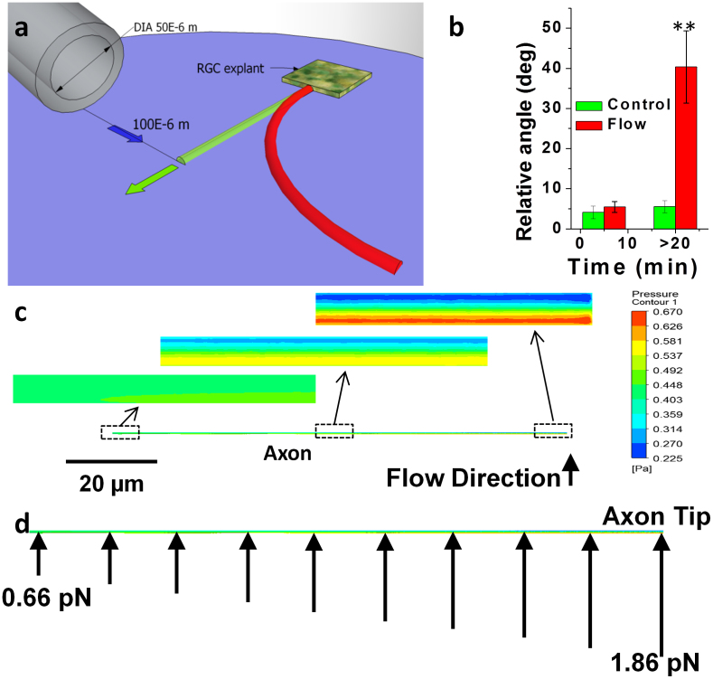
Figure 1.
(a) Petridish-view of microfluidic guidance setup. Green cylinder indicates initial orientation of axonal and growth cone, while green arrow indicates initial outgrowth direction. Red cylinder indicates final orientation of axonal shaft and growth subsequent to application of microfluidic flow (Blue arrow: flow rate: 2.5 μL/min). (b) Histogram of axonal turning angle in absence (control) and presence of microfluidic flow at two different time points (n = 8). The error bars around mean represent standard error of the mean. (c) Simulation of radial force distribution on axon induced by microfluidic flow at various axial positions, (d) estimated total force on axonal elements induced by microfluidic flow along length of axon. Magnitude of force is depicted by length of arrow.

