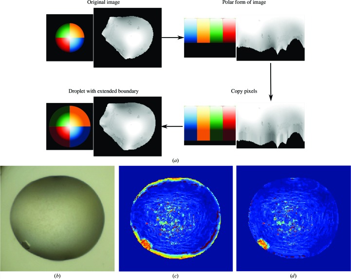
Figure 9.
(a) Process of extending the boundary of a droplet. A colour wheel is shown beside the droplet for illustration. The segmented droplet is cropped and converted to its polar form. The droplet boundary is extended by replacing 13 pixels beyond the boundary in each column with the median of intensities in the ten pixels closest to the boundary in the corresponding column. The image is finally converted back to Cartesian space. The padded pixels should be similar to the boundary they were derived from, with some variations owing to interpolation errors. (b, c, d) Effects of droplet boundary. (b) A typical example of crystal growth at the edge of the droplet. (c) The strong edge of droplet boundaries gives a strong signal that often corresponds to crystal edges, either masking the presence of crystals by the edge or creating false-positive signals. (d) By extending the droplet boundary to avoid the strong edge, noise can be supressed for better crystal detection.

