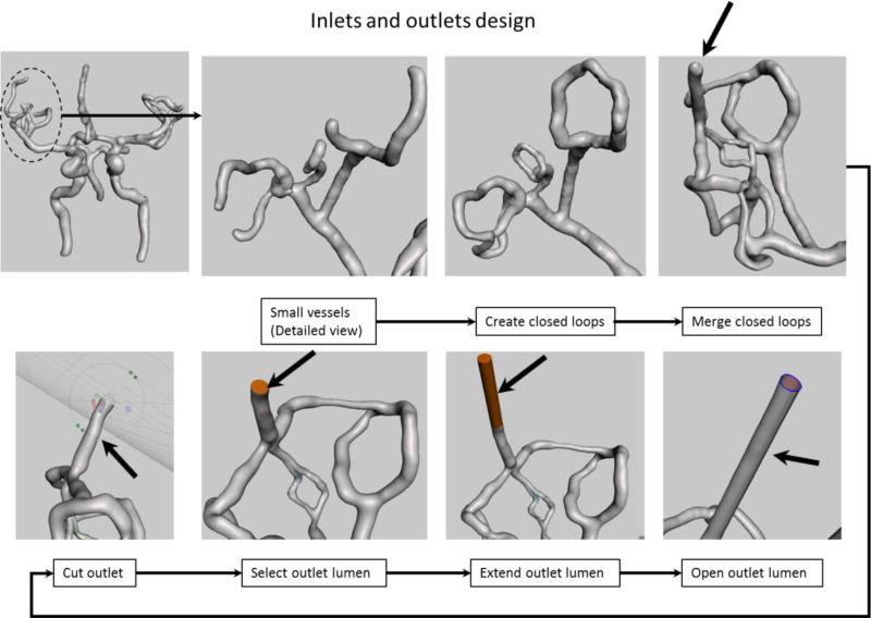
Figure 3.
Inlet and outlet design: We show the manipulation of the outlets corresponding to the right Middle Cerebral Artery Region (dotted circle). Top row shows creation of closed loops to reduce the number of outlets. Bottom row shows an extension example of one of the outlet (black arrow on last view top row) for practical reasons. The model orientation in the lower row was changed to give a better view of the intermediate steps required to extend this particular outlet (black arrow).

