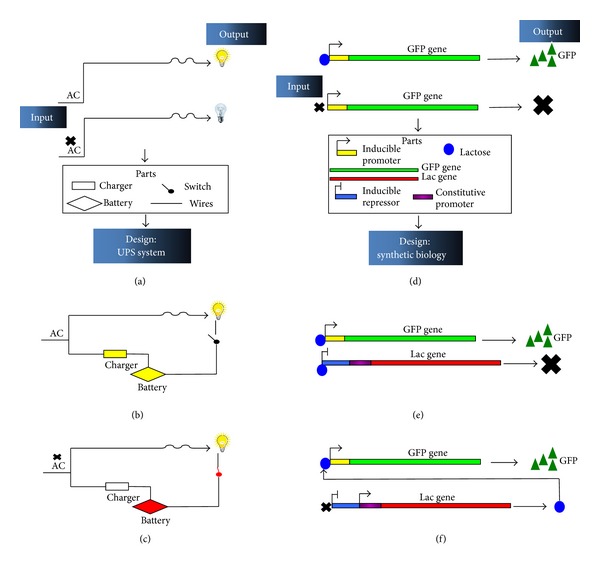
Figure 2.

A schematic representation of a comparative design of electrical and analogous biological circuit. (a) and (d) represent the initial states of the circuits in presence and absence of the input. (b), (c), (e), and (f) represent the designed circuit, addressing the issue raised by the “wild type” design of (a) and (d) when the input signal is interrupted or is not present.
