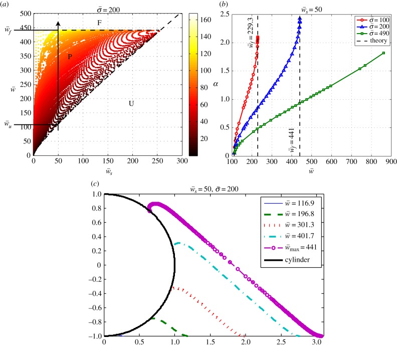
Figure 3.
(a) The phase space of the engulfment of the cylindrical object (for  ) showing the different wrapping regimes in the parameter space of
  . The colour bar in the right panel shows different colours corresponding to the engulfment angle, which is shown in degrees. The letters F, P, and U stand for fully wrapped, partially wrapped and unwrapped, respectively. The dashed lines show the analytical boundaries discussed in §3.2. (b) Variation of the wrapping angle α with
  for different values of
  . Plot (a) corresponds to the line with triangles. The analytical results for small and large wrapping are shown as dashed lines. (c) Plot of the membrane shape for increasing target binding energy
  , following the vertical arrow in (a). (Online version in colour.)

