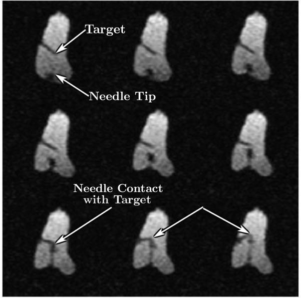
Figure 17.
Selected nine frames from continuous MRI as the needle approaches the target. The top left image shows the embedded plastic screw, the tip of which served as the target. The image also shows the entry point for the robot. Advancement of the needle is shown under continuous image guidance in the next few frames. Image on the bottom left shows the needle reaching the target with excellent accuracy. Further advancement of the needle tilts the target as shown by the blue arrows in subsequent frames.

