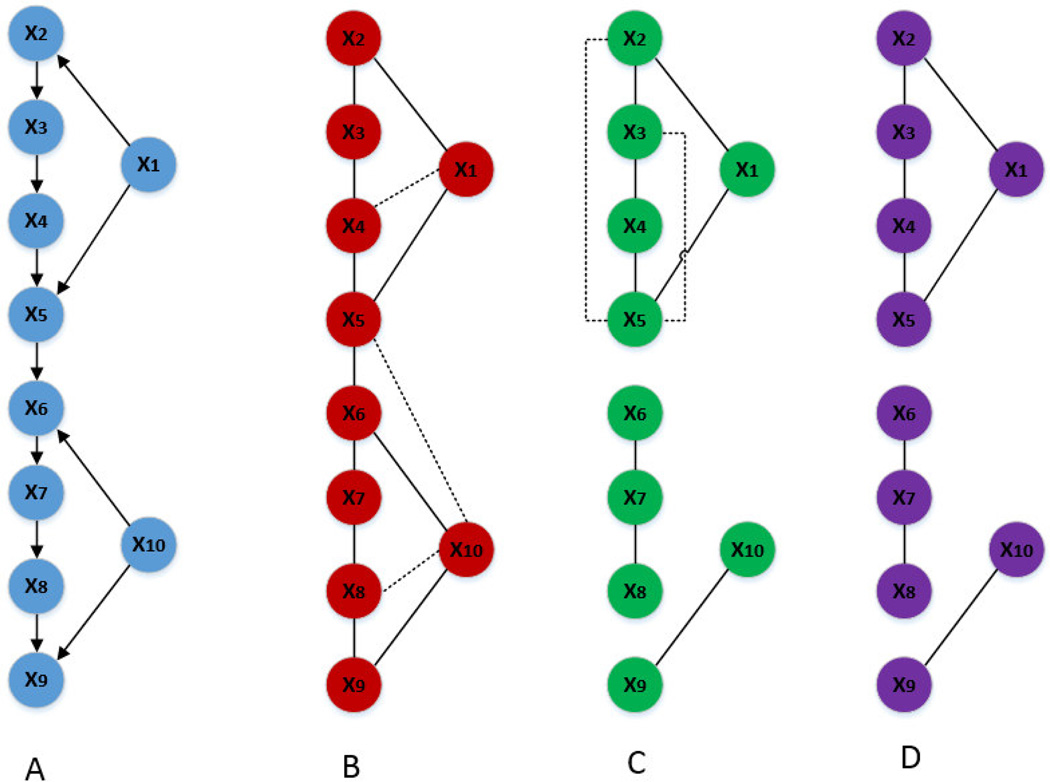
Figure 3.
Complex structure networks inferred based on GGM, 0–1 graph and LOPC. (A) The true network from the model. (B) Network inferred based on GGM: the dot lines represent the spurious edges. (C) Network inferred based on 0–1 graph (up to first order): by only conditioning on up to first order, the resulting inferred network has similar number of spurious edges (false positives) as that from GGM but has several missed edges (false negatives). (D) Network inferrred based on LOPC (up to second order): while the missed edges are inherited from 0–1 graph, calculating up to the second order successfully removes spurious edges in the inferred network.

