Abstract
Adsorbed on a solid surface, a molecule can migrate and carry an electric dipole moment. A nonuniform electric field can direct the motion of the molecule. A collection of the same molecules may aggregate into a monolayer island on the solid surface. Place such molecules on a dielectric substrate surface, beneath which an array of electrodes is buried. By varying the voltages of the electrodes individually, it is possible to program molecular patterning, direct an island to move in a desired trajectory, or merge several islands into a larger one. The dexterity may lead to new technologies, such as reconfigurable molecular patterning and programmable molecular cars. This paper develops a phase field model to simulate the molecular motion and patterning under the combined actions of dipole moments, intermolecular forces, entropy, and electrodes.
Keywords: self-assembly, diffusion, adsorbate, electric dipole
When a molecule from vacuum adsorbs on a solid surface, the total energy of the molecule and the solid reduces by an amount. Provided this binding energy is much larger than the thermal energy, the molecule will stay adsorbed on the solid surface. Under no external field, the adsorbate performs a random walk on the surface, as observed by using the field-ion microscope (1) and the scanning tunneling microscope (2, 3). The motion is thermally activated, its rate depending on the ratio of the migration barrier energy to the thermal energy.
The adsorbate carries an electric dipole moment. Even if the molecule is symmetric and nonpolar when isolated in vacuum, the act of binding to a substrate breaks the symmetry. The resulting asymmetric charge distribution gives rise to an electric dipole moment. (The clean solid surface itself has an asymmetric charge distribution. What concerns us is the excess dipole moment induced by the adsorbate.) A polar group can also be incorporated into the molecule to add a large electric dipole moment (4).
Electric field-directed adsorbate motion has been demonstrated experimentally for cesium atoms on a doped GaAs substrate surface (5). Each adsorbate induced an electric dipole moment normal to the substrate surface. A scanning tunneling microscope tip was positioned at a distance above the substrate surface. When a voltage is applied between the probe tip and the substrate, the electric field near the substrate is normal to the substrate surface and is concentrated at the spot beneath the probe tip. The nonuniform electric field acted on the electric dipoles, and it motivated the cesium atoms to migrate to the spot on the substrate surface below the probe tip. Electric field-directed motion has also been observed for adatoms on metal surfaces (6) and for lipids on air/water interface (7).
The probe tips have also been used to push molecules on solid surfaces (3, 8). The distinction between pushing and electric field-induced motion may be blurred at the nanometer scale, but does have a significant consequence. Pushing is a serial process: the probe tip has to be in contact with the individual molecules, one at a time. The electric field-induced motion can be made a parallel process. For example, a conductor mask with topographic features can be fabricated, and placed at a small gap above the substrate surface. When a voltage is applied between the substrate and the mask, the electric field is more intense beneath protruding parts of the mask surface than recessive parts. The nonuniform electric field transfers the topographic pattern on the mask to the adsorbate pattern on the substrate. The adsorbates move, but the electrodes do not. This pattern transfer process has been simulated numerically (9), and it resembles the experiments of electric-field-induced pattern formation in liquid films (10, 11).
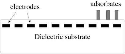
The above design requires placing the mask at a small gap above the substrate, which can be challenging in practice. Fig. 1 illustrates a different electrode design, which has been used to transport bulk liquids on a chip (e.g., ref. 12). In this design, molecules adsorb on a dielectric substrate surface, beneath which an array of electrodes is buried. Program the voltages of the electrodes individually, and the resulting electric field will direct the motion of the adsorbates. This design requires an array of nanoscale electrodes. Integrated circuits today contain feature sizes below 100 nm. Methods to fabricate complex structures of nanometer feature sizes are under intense development. This article assumes that nanoscale electrodes will become available, simulates the use of such electrodes to program the adsorbate motion, and discusses the potential of reconfigurable molecular patterns and programmable molecular cars.
Fig. 1.
A dielectric substrate has molecules adsorbed on its surface and an array of electrodes buried beneath the surface. The adsorbates carry electric dipole moments. Varying the voltage of the electrodes individually, one can program the motion of the adsorbates.
Patterns induced by elastic, electric, and magnetic fields have been studied in many systems (13–16). In particular, ferrofluids (i.e., colloidal suspensions of magnetic particles in liquids) can form various patterns in magnetic fields (17–21). Different systems share similar phenomenology and theory. Building on the existing work, our model highlights the role of patterned electric field.
A Phase Field Model of Adsorbate Motion Driven by Multiple Forces
Multiple thermodynamic forces drive adsorbate motion. The thermal energy motivates the adsorbates to distribute evenly on the surface. The interadsorbate attraction (e.g., the van der Waals force) motivates the adsorbates to aggregate into islands. The electric dipole moments of the adsorbates are aligned in the same direction. The repulsion between the dipoles limits the island size. The electrodes interact with the electric dipoles to guide the adsorbate motion. To account for these forces, we do not follow the motion of individual adsorbates, but instead develop a phase field model (22).
The space above the substrate can be vacuum or a dielectric fluid. We will refer to the top space as fluid, and the dielectric substrate as solid. The solid surface coincides with the coordinate plane (x1, x2). Let C be the coverage, i.e., the fraction of the surface sites occupied by the adsorbates. Represent the adsorbate distribution by the time-dependent field C(x1, x2, t). During the time of interest, we assume that no additional molecules adsorb to, and none desorb from, the surface. The area-average coverage, C0, is time independent.
The adsorbates may form a single phase or separate into two phases. The outcome depends on the magnitude of the interadsorbate attraction relative to the thermal energy. We describe the binary mixture of the occupied and the vacant surface sites as a regular solution. The free energy of mixing per unit surface area is
 |
[1] |
where Λ is the number of surface sites per unit area, kB is the Boltzmann constant, T is the absolute temperature, and Ω is the dimensionless parameter that measures the interadsorbate attraction relative to the thermal energy. The first two terms in the bracket come from the entropy of mixing, and the third term comes from the enthalpy of mixing. When Ω < 2, the thermal energy prevails, the function g(C) has a single well, and the binary mixture forms a solution. When Ω> 2, the interadsorbate attraction prevails, the function g(C) has double wells, and the binary mixture separates into two phases. While the regular solution model is one of many solution models that can be invoked, it does have the ingredients essential to the phenomenon.
Next we incorporate the dipole–dipole and the dipole–electrode interactions into the model. Let ψ(x1, x2, x3, t) be the electric potential field. When distinction is needed, the field in the fluid is denoted by ψf and the field in the solid by ψs. The adsorbate mobility on the surface is low compared with the charge mobility in the electrodes. At a given time, with a given distribution of the adsorbates, the electric field is governed by electrostatic equations. We assume that no excess charge exists inside the dielectric fluid and solid, so that the electric potential obeys the Laplace equation.
The electric dipoles of the adsorbates cause a change in the surface potential, which can be measured experimentally by using the Kelvin method (23). We assume that the surface potential is linear in the adsorbate coverage. That is, at the fluid/solid interface, x3 = 0, the electric potential jumps
 |
[2] |
The slope ζ is a material constant. This boundary condition couples the electrostatic field to the adsorbate distribution.
We assume that the adsorbates are electrically neutral, and no excess charge exists on the fluid/solid interface. Consequently, the electric displacement component normal to the interface, D3, is continuous across the interface:
 |
[3] |
where εf and εs are the permittivity of the fluid and the solid.
We will not treat the electrodes buried beneath the dielectric substrate surface as discrete individuals. Instead, we assume that the electrode array provides a programmable electric potential field at depth H beneath the dielectric surface:
 |
[4] |
where U represents the voltage magnitude, and s represents the time-dependent electrode voltage pattern. The Laplace equation, together with the boundary conditions, determines the electric potential field.
The driving force on an adsorbate, f, is the reduction of the free energy of the system associated with the adsorbate moving a unit distance. Following the procedure in ref. 22, we obtain that
 |
[5] |
The driving force consists of several terms. The first term comes from the free energy of mixing, which accounts for the thermal energy and the interadsorbate interaction. The second term represents the Cahn–Hilliard gradient energy (24), where h is a constant. The third term accounts for the dipole–dipole and dipole–electrode interactions.
Let J be the adsorbate flux, i.e., the number of adsorbates crossing a line of unit length on the substrate surface per unit time. Assume that the adsorbate flux is linearly proportional to the driving force, J = Mf, where M is the adsorbate mobility. The conservation of the adsorbates requires that Λ∂C/∂t = –▿·J. These considerations, together with Eq. 5, lead to the diffusion equation:
 |
[6] |
The third term in the bracket couples the evolution of the adsorbate distribution to the electrostatic field.
The above model simultaneously evolves the adsorbate distribution field C(x1, x2, t) and the electric potential field ψ(x1, x2, x3, t). At a given time, the adsorbate distribution field is known. The electrostatic field is determined by solving the boundary value problem. The resulting electric displacement enters the right-hand side of Eq. 6, which updates the adsorbate distribution field for a small time step. When this procedure is repeated for many time steps, the two fields evolve over a long time.
Computational Method
A comparison of the first two terms in the parenthesis in Eq. 5 defines a length:
 |
[7] |
In the Cahn–Hilliard model (24), this length scales the distance over which the coverage changes from the level of one phase to that of the other. The length b may be considered the width of the phase boundary.
From Eq. 6, disregarding a dimensionless factor, we note that the diffusivity scales as D ∼ MkBT/Λ. To resolve events occurring over the length scale of the phase boundary width, b, the time scale is τ = b2/D, namely,
 |
[8] |
We normalize the spatial coordinates by b and the time by τ. A dimensionless number,
 |
[9] |
appears in the normalized equation. The number W represents the magnitude of the molecular dipole moment relative to the intermolecular attraction, and it affects the equilibrium island size.
A main difficulty in the algorithm outlined in the previous section is that, at every time step, the electrostatic boundary value problem has to be solved, which is time consuming. For our problem, involving two layers of dielectrics, the electrostatic boundary value problem can be solved analytically in the Fourier space. Take the Fourier transform of a function with respect to the two coordinates x1 and x2, for example,
 |
[10] |
where k1 and k2 are the coordinates in the Fourier space. In the Fourier space, the Laplace equation becomes an ordinary differential equation  , where
  . The solution takes the form ψ = Aexp(3) + Bexp(–kx3), with one pair of constants A and B for fluid, and another pair for the solid, all being determined by the boundary conditions. The solution gives the electric displacement at the fluid/solid interface:
 |
[11] |
In the Fourier space, the diffusion Eq. 6 becomes
 |
[12] |
Here both k and H are normalized by b, t is normalized by τ, and P̂(k1, k2) is the Fourier transform of the function
 |
[13] |
Eq. 12 has a structure typical for phase field models. A commonly used numerical procedure (25) will be adopted here. The substrate surface is divided into periodic square cells. The computation is carried out in a single cell. The cell is further divided into 256 × 256 grids. We evolve the values of the C-field at all of the grid points. At a given time, the C values are known in both the real and the Fourier spaces. Calculate the nonlinear function P at all of the grid points in the real space according to Eq. 13 and transform them into the Fourier space. Update Ĉ at all grid points in the Fourier space according to Eq. 12, and perform the inverse Fourier transform to obtain C values in the real space. Repeat this procedure for many time steps. The C values are plotted in the computation cell in the real space, using a gray scale.
The model has many dimensionless numbers: Ω, W, εs/εf, H/b, U/ζ, and the average coverage C0. In addition, the initial adsorbate distribution field is spatially dependent, and the electrode voltage pattern is spatially and time dependent. A survey of the full parameter space is beyond the scope of this paper. In the following numerical examples, unless otherwise noted, we set Ω = 2.2, W = 2, εs/εf = 1, and H/b = 10. For the value Ω = 2.2, the free energy of mixing g(C) has two wells at the coverage C = 0.25 and C = 0.75. To illustrate several considerations, we will vary U/ζ, the initial adsorbate distribution, and the electrode voltage pattern.
Self-Assembled Molecular Patterns
First consider adsorbates on a dielectric substrate surface, with no electrodes buried beneath. The adsorbate patterns self-assemble, responding to the actions of the free energy of mixing, the gradient energy, and the surface potential. When the adsorbates separate into two phases, the phase boundary energy drives the phases to coarsen. The molecular dipole moments are aligned in the same direction: they repel one another. Consequently, the dipole–dipole interactions drive the phases to refine. In equilibrium, the phases will reach equilibrium sizes, typically ranging from nanometers to micrometers (13–22). The following examples illustrate the coarsening and refining actions.
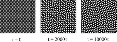
Fig. 2 shows a time sequence initiated with an array of islands of radius ≈2.5b, which is smaller than the equilibrium island size. The average coverage is C0 = 0.42. At t = 0, C = 0.75 for the islands, and C = 0.25 for the background. The initial adsorbate distribution field also has a random fluctuation of magnitude 0.001. In subsequent times, the islands coarsen and reach the equilibrium phase size. During coarsening, some islands enlarge, and others shrink, so that initial order disappears. Upon reaching the equilibrium size, the islands begin to order into a triangular lattice. The new order starts locally and spreads over time.
Fig. 2.
In the absence of the electrodes, the adsorbates self-assemble into islands. This time sequence starts with a lattice of circular islands with a diameter below the equilibrium island diameter. The islands coarsen to reach the equilibrium size.
Fig. 3 shows a time sequence initiated with an array of large islands, of radius ≈30b. All other parameters are the same as used for Fig. 2. The large circular island is unstable. Fingers emerge, and quickly reach the equilibrium feature size. The finger morphology is stable during the time period simulated. The fingering process has been studied in ferrofluids (18). The fingers are metastable. When thermal energy is large enough, the fingers may break into dots. Our model lacks thermal noise, so that the fingers are trapped in the metastable states.
Fig. 3.
Self-assembled pattern in the absence of electrodes. This time sequence starts with a lattice of islands with a diameter larger than the equilibrium island diameter. The pattern refines to approach the equilibrium feature size. Figures emerge and remain stable.
Symmetry has profound effects on pattern formation. Our model is isotropic, so that island lattices of all orientations are equally possible. In the above examples, even though the initial adsorbate distributions are ordered, the order disappears as the patterns evolve. Gaining new order takes a long time. Also, self-assembly will never produce any specific nonperiodic pattern on demand. To produce a specific pattern on demand, a template must be used. We next use the electrode voltage pattern to direct the adsorbate pattern formation.
Electric Field-Directed Patterning
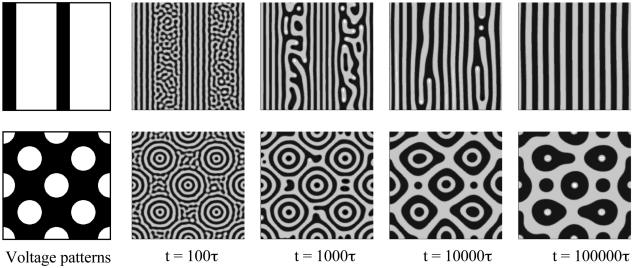
Fig. 4 shows two time sequences, guided by different electrode voltage patterns, the upper row by an array of stripes, and the lower row by a lattice of dots. At t = 0, adsorbates distribute uniformly, with coverage C0 = 0.5. A small magnitude of the electrode voltage, U/ζ = 0.02, is prescribed. In the absence of the electrode voltage pattern, the adsorbates at the average coverage C0 = 0.5 self-assemble into a pattern of noodles (e.g., ref. 22). As illustrated in Fig. 4, the small-magnitude electrode voltage patterns can guide the adsorbates to form straight stripes and other patterns.
Fig. 4.
Two examples of electric field-guided patterning. The electrode voltage pattern is an array of stripes in Upper and an array of dots in Lower. In both cases, the amplitude of the electrode voltage is small, so that adsorbates still retain the natural pattern of fine stripes, and the electrode voltage pattern affects the overall layout. Note that the feature sizes of the electrode voltage pattern are different from the equilibrium features of the adsorbate patterns.
The electrode voltage pattern can be changed at any time, so that the adsorbate pattern is reconfigurable. Fig. 5 shows a time sequence. The initial adsorbate distribution is uniform, with coverage C0 = 0.35. Prescribe the electrode array with a voltage pattern of the letter P in a relatively high voltage, U/ζ = 1. Under the guidance of the electrode voltage pattern, the adsorbates form a pattern of the letter P. No electrode voltage is applied in the background, so that the remaining adsorbates self-assemble into islands. We then change the electrode voltage pattern into the letter H. The adsorbates reassemble to form the letter H. The newly assembled pattern bears no resemblance to the old one.
Fig. 5.
Reconfigurable patterning. Initially, the electrode voltage pattern is the letter P, and the adsorbates assemble accordingly. Then switch the electrode voltage pattern to the letter H, and the adsorbates reassemble. The amplitude of the electrode voltage is high, so that the electrode voltage pattern overwhelms the natural pattern of the adsorbates.
The above examples demonstrate that a static electrode voltage pattern can either guide the self-assembly of the adsorbates or impose a desired pattern. The main difference in the two operations is the magnitude of the electrode voltage relative to the surface potential, namely, the ratio U/ζ. A small-amplitude electrode voltage pattern guides the overall layout of the stripes. The natural pattern such as the stripes is more or less preserved. A large-amplitude electrode voltage pattern overwhelms the natural pattern, and the adsorbate pattern is nearly a replica of the electrode voltage pattern.
Programmable Motion
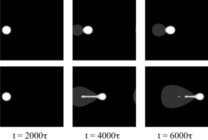
When the electrode voltage pattern is time dependent, the adsorbates will move around. For example, consider a single island of aggregated adsorbates. If the electrodes are energized sequentially, the island can be propelled to move in a desired direction. Fig. 6 shows two time sequences, using parameters U/ζ = 1 and C0 = 0.2. At such a coverage, no phase separation takes place in the absence of the external electric field. We apply a circular voltage pattern at the center. After a time of 2000τ, an island of the size similar to the voltage pattern assembles. Subsequently, we program the electrode voltage pattern into a traveling wave. Fig. 6 shows snapshots for islands driven at two electrode voltage wave velocities. When the electrode voltage wave moves slowly (v = 0.02b/τ), the island distorts somewhat but follows the voltage wave. When the electrode voltage wave moves too fast (v = 0.05b/τ), the island ruptures.
Fig. 6.
The effect of electrode voltage wave speed. (Upper) An adsorbate island driven by a slow electrode voltage wave at a low velocity. (Lower) An adsorbate island driven by a fast electrode voltage wave.
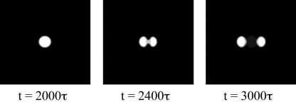
Fig. 7 shows that the electrode voltage can be programmed to split an island. The parameters used are the same as those for Fig. 6. Again, we apply a circular voltage pattern at the center. After a time of 2000τ, an island of size similar to the electrode voltage pattern forms. We then divide the voltage pattern into two halves and move them apart with a constant velocity of v = 0.025b/τ. The island also splits into two halves, which follow the two electrode voltage waves.
Fig. 7.
Splitting an island. The initial electrode voltage pattern is a circular dot. The voltage pattern is then divided into two halves and moved in opposite directions. The adsorbate island is split into two smaller islands.
When the interadsorbate attraction is strong, the electrode voltage pattern will not distort the island excessively. In a separate simulation (not shown here), we set Ω= 2.8, which gives the coverage of two equilibrium phases: C = 0.89 (the island), and C = 0.11 (the background). The island forms spontaneously, in the absence of the electrode voltage. In the subsequent motion propelled by an electrode wave, the island retains the circular shape.
The Molecular Car
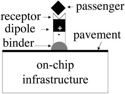
We envision a technology: the molecular car. Fig. 8 illustrates the concept. Consider a short-chain molecule with three characteristics: its one end adsorbs to a solid surface, its midchain has a group with a large electric dipole moment normal to the solid surface, and its other end is a passenger receptor. The molecule has a modular architecture. The division of labor offers the flexibility to design separate modules, at the molecular level, to fulfill distinct functions. More generally, the car can be a monolayer island, a largish molecule, or a polymer.
Fig. 8.
The molecular car has a modular architecture. The binder and the pavement ensure that the car stays on the surface and moves fast. The electric dipole moment serves the function of the engine. The receptor serves the function of the passenger seat. The on-chip infrastructure consists mainly of electrodes that control the motion of the molecular car.
The modular architecture also extends to the on-chip infrastructure. The surface of the chip can have a pavement of immobile molecules to enhance the mobility of the car, confine its Brownian motion, or prevent other molecules in the environment from littering the highway. An array of electrodes is buried underneath the surface to propel the molecular car. The space above the car can be a vacuum, a dielectric liquid, or a solid overpass. The car receives a passenger molecule in one pool, moves on the highway on the chip, and then releases the passenger molecule in another pool. Reversible molecular binding and releasing may be effected by controlling pH level or ionic concentration (26).
The molecular car can be made reconfigurable. If the car is a monolayer island with weak interadsorbate attraction, the car can split into smaller cars in response to an electrostatic force, and the cars then move in separate ways. Conversely, several cars can merge into a single larger car and allow passengers to mix. Implications for combinatorial chemistry are evident. If the car is a largish molecule or a polymer, it can change conformation in response to light, electric field, or temperature.
The concept of the molecular car raises many questions. What is it good for? Controlled matter transport has always been important to human beings. In our time, the fluidics has been reduced to the micrometer scale, enabling the lab-on-a-chip technology (e.g., ref. 27). Applications include medical diagnostics and combinatorial chemistry. The molecular car will push the fluidics to its ultimate size limit: only monolayer islands or single molecules move. In applications, fluidics of different sizes serve different functions. Channels transport large quantities of target molecules. Molecular cars transport small quantities of target molecules.
Will the electrode have the authority to control the molecular car against thermal motion? To illustrate the issue, consider the scanning probe experiment again (5). For a suitable polarity, the probe tip creates a trap in the energy landscape on the surface. The electric field changes the free energy of the adsorbate by pE, where p is the dipole moment of the adsorbate, and E is the electric field normal to the surface of the substrate (taken to be a conductor). For simplicity, we have neglected the effects of higher order in the electric field. When the tip–substrate gap, d, is small compared with the tip radius, under the voltage V, the electric field beneath the tip is approximately V/d. Consequently, the depth of the energy trap is approximately pV/d. Assume that the electric dipole results from a positive and a negative charge, of magnitude 10–19 C and separated by a distance 10–10 m, giving a dipole moment on the order p = 10–29 C·m. This estimate gives the representative order of magnitude of observed electric dipole moments (28). Assuming the voltage 1 V and gap 10–9 m between the tip and the substrate, we find that, under the probe tip, the electric field is 109 V/m, and the energy trap depth is 0.1 eV. This trap depth is larger than the thermal energy kBT = 0.025 eV at room temperature.
How fast can the molecular car move? The adsorbate binds some surface sites better than others: the energy landscape has valleys and hills. To migrate from one valley bottom to another, the molecule has to pass over the migration energy barrier, which is about one order of magnitude smaller than the binding energy. It is possible for a molecule to bind well to a substrate but still move fast. The diffusivity typically follows the relation D ∼ νa2 exp(–Em/kBT), where ν is the jump frequency, a is the jump distance, and Em is the migration energy barrier. Taking representative values, ν = 1013 s–1, a = 10–10 m, and kBT = 0.025 eV, the diffusivity is D = 10–7 exp(–40Em)m2/s. The electric field is nonuniform on the surface, with a decay length comparable to the radius of the probe tip, R. The gradient of the potential energy defines the driving force for the drift: f = p▿E. The force scales as f ∼ pV/Rd. Using p = 10–29 C·m, V = 1 V, R = 10 nm, and d = 1 nm, we obtain that f ∼ 1 pN. The drift velocity u relates to the driving force according to the Einstein relation: u = fD/kBT. The estimated order of magnitude for the drift velocity is 10–1 m/s when Em = 0.1 eV, 10–8 m/s when Em = 0.5 eV, and 10–8 m/s when Em = 1.0 eV. So long as the migration energy barrier is low, the molecular car moves fast.
Concluding Remarks
Adsorbed on a solid surface, a molecule carries an electric dipole moment and moves on the surface by a thermally activated process. An electrode can direct the motion of the molecule. When a collection of the molecule partially covers the solid surface, their motion is influenced by the entropy, the intermolecular attraction, the dipole–dipole interaction, and the dipole–electrode interaction. We develop a phase field model to evolve the adsorbate distribution field under the multiple thermodynamic forces. An array of electrodes can be programmed to guide the assembly of the adsorbates or move the adsorbates in desired ways. Our numerical simulation illustrates the potential of the programmable adsorbate motion for reconfigurable assembly and a molecular car.
In initiating any scientific and engineering endeavor, such as creating the molecular car, we may ask, why now? Tantalizing applications aside, the answer has to do with the confluence of new tools. The invention of scanning probes has led to unprecedented control and visualization of molecular motion. Specifically, the probe tip can be used to search for suitable molecular car components and pavements. Chemical synthesis techniques now exist to incorporate bioreceptors and other functional groups into a single molecule. The fabrication technology can now make nanoscale features envisioned for the on-chip infrastructure for the molecular car. Integrated circuits are massproduced with features below 100 nm; features below 10 nm can be made in laboratories. Computational power makes it possible to design the molecular car and its on-chip infrastructures. The creation and development of the molecular car will benefit from, and ultimately challenge, all these tools.
Acknowledgments
We gratefully acknowledge discussions with D. Chen, of Rowland Institute at Harvard, and Z. Zhang, of Oak Ridge National Laboratory. This project was initiated under the support of the National Science Foundation through the Materials Research Science and Engineering Center (MRSEC) at Princeton University. Our work in this area has been supported by the Department of Energy through Grant DE-FG02-03ER46091, and by the Division of Engineering and Applied Sciences at Harvard University.
This paper was submitted directly (Track II) to the PNAS office.
References
- 1.Kellogg, G. L. (1994) Surf. Sci. Rep. 21, 1–88. [Google Scholar]
- 2.Barth, J. V. (2000) Surf. Sci. Rep. 40, 75–149. [Google Scholar]
- 3.Rosei, F., Schunack, M., Naitoh, Y., Jiang, P., Gourdon, A., Laegsgaard, E., Stensgaard, I., Joachim, C. & Besenbacher, F. (2003) Prog. Surf. Sci. 71, 95–146. [DOI] [PubMed] [Google Scholar]
- 4.Evans, S. D., Urankar, E., Ulman, A. & Ferris, N. (1991) J. Am. Chem. Soc. 113, 4121–4131. [Google Scholar]
- 5.Whitman, L. J., Stroscio, J. A., Dragoset, R. A. & Gelotta, R. J. (1991) Science 215, 1206–1210. [DOI] [PubMed] [Google Scholar]
- 6.Tsong, T. T. & Kellogg, G. (1975) Phys. Rev. B 12, 1343–1353. [Google Scholar]
- 7.Lee, K. Y. C., Klingler, J. F. & McConnell, H. M. (1994) Science 263, 655–658. [DOI] [PubMed] [Google Scholar]
- 8.Heinrich, A. J., Lutz, C. P., Gupta, J. A. & Eigler, D. M. (2002) Science 298, 1381–1387. [DOI] [PubMed] [Google Scholar]
- 9.Gao, Y. F. & Suo, Z. (2003) J. Appl. Phys. 93, 4276–4282. [Google Scholar]
- 10.Chou, S. Y. & Zhuang, L. J. (1999) Vac. Sci. Technol. B 17, 3197–3202. [Google Scholar]
- 11.Schaffer, E., Thurn-Albrecht, T., Russell, T. P. & Steiner, U. (2000) Nature 403, 874–877. [DOI] [PubMed] [Google Scholar]
- 12.Velev, O. D., Prevo, B. G. & Bhatt, K. H. (2003) Nature 426, 515–516. [DOI] [PubMed] [Google Scholar]
- 13.Seul, M. & Andelman, D. (1995) Science 267, 476–483. [DOI] [PubMed] [Google Scholar]
- 14.Ng, K.-O. & Vanderbilt, D. (1995) Phys. Rev. B 52, 2177–2183. [DOI] [PubMed] [Google Scholar]
- 15.Plass, R., Last, J. A., Bartelt, N. C. & Kellogg, G. L. (2001) Nature 412, 875. [DOI] [PubMed] [Google Scholar]
- 16.Lu, W. & Suo, Z. (2001) J. Mech. Phys. Solids 49, 1937–1950. [Google Scholar]
- 17.Rosensweig, R. E. (1985) Ferrohydrodynamics (Cambridge Univ. Press, Cambridge, U.K.).
- 18.Dickstein, A. J., Erramilli, S., Goldstein, R. E., Jackson, D. P. & Langer, S. A. (1993) Science 261, 1012–1015. [DOI] [PubMed] [Google Scholar]
- 19.Hong, C.-Y., Chen, C. A., Chen, C.-H., Horng, H. E., Yang, S. Y. & Yang, H. C. (2001) Appl. Phys. Lett. 79, 2360–2362. [Google Scholar]
- 20.Friedrichs, R. & Engels, A. (2001) Phys. Rev. E 64, 021406-1–021406-10. [DOI] [PubMed] [Google Scholar]
- 21.Richardi, J., Ingert, D. & Pileni, M. P. (2002) Physical Rev. E 66, 046306-1–046306-10. [DOI] [PubMed] [Google Scholar]
- 22.Suo, Z., Gao, Y. F. & Scoles, G. (2004) J. Appl. Mech., 71, 24–31. [Google Scholar]
- 23.Sessler, G. M., ed. (1987) Electrets (Springer, Berlin).
- 24.Cahn, J. W. & Hilliard, J. E. (1958) J. Chem. Phys. 28, 258–267. [Google Scholar]
- 25.Chen, L. Q. & Shen, J. (1998) Comput. Phys. Commun. 108, 147–158. [Google Scholar]
- 26.Lawrence, D. S., Jiang, T. & Levett, M. (1995) Chem. Rev. 95, 2229–2260. [Google Scholar]
- 27.Meldrum, D. R. & Holl, M. R. (2002) Science 297, 1197–1198. [DOI] [PubMed] [Google Scholar]
- 28.Israelachvili, J. (1991) Intermolecular and Surface Forces (Academic, New York).


