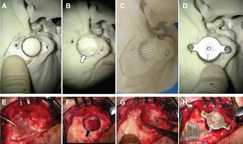
Figure 3.
An actual STAMP plate-guided Bonebridge (BB) implantation: (A–D) simulation; (E–H) operation. A temporal bone replica generated from this patient’s CT data was used for this simulation. (A, E) Marking the correct place for BB implantation. The BB-STAMP plate fits only one place on either of the bony surfaces. (B, F) After drilling out of an adequate size of bony hollow. The sigmoid sinus was exposed by the operation (black arrow in F) as was predicted by the simulation (white arrow in B). (C, G) Confirming the hole size and place using the C-STAMP plate. Whether there is enough depth at the right angle can be determined. (D, H) Fixation of the BC-FMT. The transducer fits the hole well and the screw has been fixed to the correct position. BC-FMT, bone conduction-floating mass transducer; C-STAMP, the C-STAMP can check whether the hole is an appropriate size for the BC-FMT.

