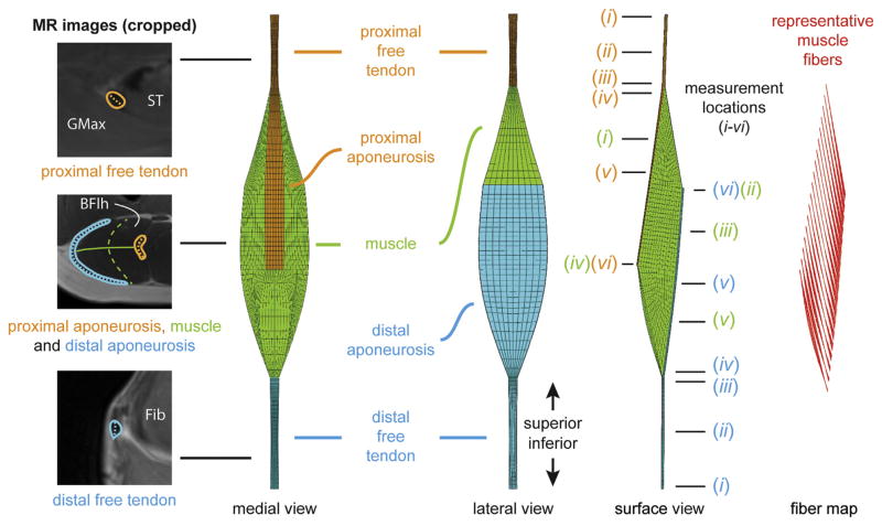
Fig. 1.
BFlh musculotendon measurements and FE mesh. The dimensions of FE computational meshes were based on musculotendon measurements on MR images. Width measurements for the tendon and muscle are indicated as dashed lines on the three cropped MR images. The solid line on the middle cropped MR image indicates the muscle thickness measurement. The FE mesh has three materials: proximal tendon/aponeurosis, muscle and distal tendon/aponeurosis. Measurement locations for each material are indicated with a line and are numbered according to the description in the text. Representative muscle fibers were mapped through the FE mesh to define initial fiber direction at each element and calculate spatially varying local tissue strain (Blemker and Delp, 2005). MR: magnetic resonance. ST: semitendinosus. GMax: gluteus maximus. BFlh: biceps femoris long head. Fib: fibula.

