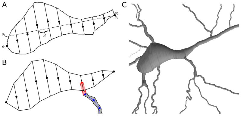
Figure 6.
(A) Sliced soma outline: major axis (dashed); centers of skew frusta ends (dots). (B) Due to measurement and reconstruction errors, a dendrite (gray) defined by a set of nodes (blue) might not touch the reconstructed soma. To fix this, CTNG adds an additional point (red) to the dendrite definition chosen from the centers of the skew frusta faces (black dots). Conceptually this adds the pink region to the dendrite definition, however only the portions lying outside the soma contribute additional surface area and volume due to the constructive cubes approach. (C) CTNG’s 3D interpretation with dendritic attachments.

