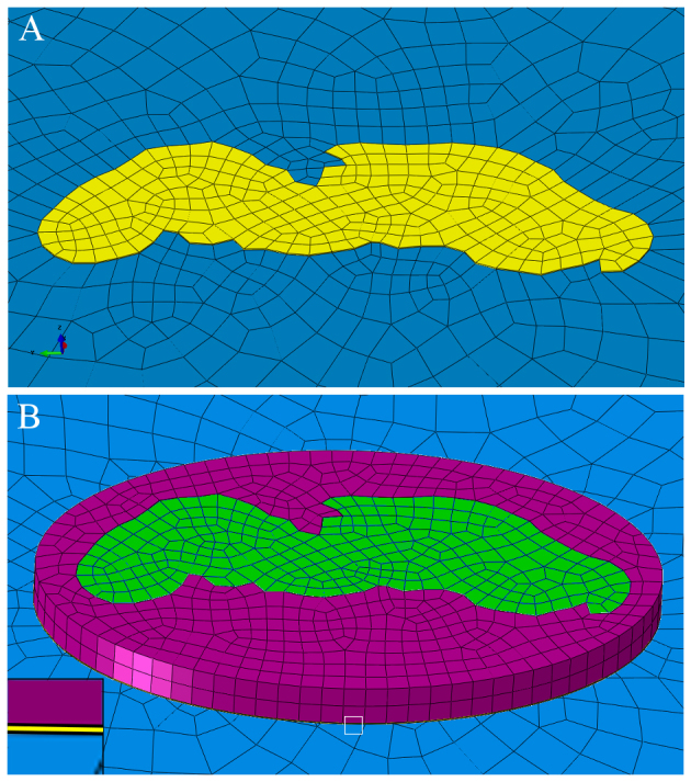
Fig. 8.

CGI and CGII using the examples of the finite element models prepared to analyse the tensile test ‘transversal 3’. (A) CGI consisting of a 400 nm thick cuticle (yellow) contacting the latex membrane (blue). The mesh of the cuticle is connected to that of the latex membrane. (B) CGII consisting of four parts: a 400 nm thick cuticle of the same geometry as the cuticle in CGI, which stays in contact with the latex membrane and on top of this a second 14.8 μm thick layer (green), which represents the layers of the contact zone in the arolium from the procuticle to the epidermis. These two cuticle layers are encircled by two surroundings (yellow and violet) showing the same material properties as the cuticle layers of the same thickness. The mesh of the surrounding of the thin cuticle layer is not connected to that of the latex membrane. The inset in image B shows the surrounding of the 400 nm thin cuticle layer in detail. The magnified area is highlighted by a white square.
